I have made my own composite of triple ply corrugated cardboard faced with foam core all held together with either 777 Fastack or latex caulking for CLD dampening.
Latex caulking and Fastack are not viscoelastic and will not work in a constrained layer damping application. For built in CLD effects in the cabinet, here are a few products you may want to consider. I am not affiliated with any of them, I just have researched DIY CLD quite a bit.
3M Scotchdamp tape
Green Glue
Pitch
ArtUSA acoustic adhesive
Various car audio CLD products
Misc Chinese products
Remember the viscoelastic layer should be thin, as it must undergo shear forces in order to heat up. Ideally, you want it coupled to a substrate that can dissipate that heat quickly, so that more of a damping effect is realized. That is why the car audio product and the 3m product attach a thin layer of aluminum foil, which carries heat well. In our foam core application, I think the best way to do this would be to spread the viscoelastic material on the most rigid surface. In your case, these would be the cardboard sheets. Then on top, put one layer of aluminum foil. Then use a standard adhesive and attach a layer of foam.
I hope this helps with your cabinet. 🙂
Last edited:
Also any product with butyl rubber will work. That's what they use for car audio. I found this on Amazon just now - a roll of butyl tape with foil already applied.
It's cheaper than butyl by itself and already backed with foil.
update: Actually I just compared prices and the car stuff is way cheaper. You get 9 square feet on that roll vs 36 sq ft for this at only a minor price bump.
There is already good data out there on CLD effectiveness for car audio, as well.
Last edited:
I am using the Noico butyl rubber with aluminum sheet in wooden cabinet speaker - good stuff. The foil is to keep it from being sticky on side you want clean. It's too flexible to be of use for constrained layer damping as it just flexes or buckles. I will try it on foam core. I am sure it will make a big difference with all the mass that is added.
I recently won some MCM 3" full range speaker as a door prize, really excited to experiment with them! Do you use any sort of calculator or equation to come up with your designs, or MLTL lengths? I'm a bit at a loss as to how to start building various foam board enclosures. I was thinking of a cornu spiral, possibly a floor standing MLTL, backloaded horn, etc. Just to experiment.
Link to the driver: MCM Audio Select 3" Die Cast Woofer 8 Ohm Rubbber Surround Phase Plug | 55-5650 (555650) | MCM Audio Select
Link to the driver: MCM Audio Select 3" Die Cast Woofer 8 Ohm Rubbber Surround Phase Plug | 55-5650 (555650) | MCM Audio Select
Klampykixx,
Some sketches or pictures of what you are trying to do would be helpful.
hi, sorry about the "in and out" ness nature of my visits, im currently playing with 3d printing a scale version of my SS15 horn to play with and now that im happy enough that i can model that, im almost certain ill be modelling some more to achieve the micro folded horn using 35mm drivers and printing them off, kinda going away from the foam core concept, but should be interesting none-the-less
hi, sorry about the "in and out" ness nature of my visits, im currently playing with 3d printing a scale version of my SS15 horn to play with and now that im happy enough that i can model that, im almost certain ill be modelling some more to achieve the micro folded horn using 35mm drivers and printing them off, kinda going away from the foam core concept, but should be interesting none-the-less
Long time no hear my friend. Good to have you back. I'm all for 3D printing too and use it extensively now in my speakers. Check this one out.
http://www.diyaudio.com/forums/multi-way/285030-bookshelf-multi-way-point-source-horn.html
I can't get foamcore over here, but I found blue foam boards. Do I qualify? 😉
I'm starting a new project of a FAST system with a sealed sub and a fullrange on top.
More info here:
http://www.diyaudio.com/forums/full-range/301601-small-ob-fast-setup.html
I'm starting a new project of a FAST system with a sealed sub and a fullrange on top.
More info here:
http://www.diyaudio.com/forums/full-range/301601-small-ob-fast-setup.html
Attachments
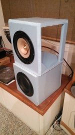
That looks like XPS foam board and sure it qualifies as foam core speaker!
Looks nice! Is that Tang Band 8in with whizzer?
Looks nice! Is that Tang Band 8in with whizzer?
I've done a bit of searching and couldn't find much about a folded (stepped) circular horn. Has anyone ever done or heard of this? The simple implementation would have parallel front and rear baffles with circular, perpendicular internal dividers of specific height on each baffle that determine the horn cross section area and length. It might be easiest to visualize a spawn horn design, but not as large and with different dimensions, rotated around 360 degrees.
From a construction standpoint, the front and back halves could be built independently (making it easier to do with wood or foam core board) and then mechanically coupled together using dowels or other sections of material at various places in the horn path.
This design would make the cylindrical mouth area of the horn pi*d*h, where d is the outer circumference of the enclosure and h is the height between the inside of the front and rear baffle surface. For a 0.15m (5.9 in) depth folded circular horn with a diameter of 1m, the total mouth area is 0.47m, which corresponds to a cutoff frequency of 141.4Hz (according to MJK's horn physics documents) if you only consider the height between the front and rear baffles. However, if you place the enclosure flat against a wall it effectively extends the horn mouth and lowers the cutoff frequency.
Last edited:
would that horn be like a circular version of Frazier's "Dixielander" ? - the silver "cone" was made of wood
Dwgs for Frazier Dixieland Cabinets
Dwgs for Frazier Dixieland Cabinets
Wow that's complicated.
I have seen something resembling a spiral made with just square angles and one a flat speaker. Kind of like a Cornu but with one length and not two paths. Is that what you are talking about?
I have seen something resembling a spiral made with just square angles and one a flat speaker. Kind of like a Cornu but with one length and not two paths. Is that what you are talking about?
I apologise if this has been asked somewhere in the 284 pages of this thread: but has anyone tried bituminous damping (eg like ls3/5a) on foamcore. I was thinking in terms of a 4 or 5 litre cabinet
would that horn be like a circular version of Frazier's "Dixielander" ? - the silver "cone" was made of wood
Dwgs for Frazier Dixieland Cabinets
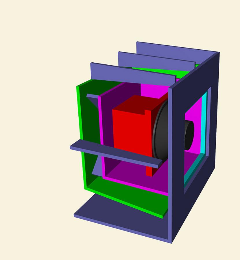
The Dixielander design is rear firing but the concept appears to be similar. A CAD sketch of a potential cross section of what I mentioned is attached. The horn's mouth is side firing like the Cornu, and the mouth area is the entire diameter, but there are no internal spirals. The horn path has many 180 degree bends, which should help reduce any higher frequencies from getting out of the horn and make it easier to build. The only bad part about the design is that the driver is positioned dead center on a circular baffle which is the worst possible baffle shape and mounting position. That could possibly be cured by extending the compression chamber outward and mounting the driver away from the top baffle. You could then use a supra baffle of a better size/shape.
You could even include the cone at the back of the compression chamber like in the Dixieland design.
Attachments
Last edited:
Wow that's complicated.
Is it a bunch of 5 sided boxes held together by the bracing?
the solvents in the mastic might degrade the foam !
Good point. Let's assume then that I varnish the foamcore surfaces.
The foam core is paper lined.
Oh. Can't paper be varnished.
As long as varnish is not solvent containing that would melt foam. The paper is absorbent and if absorbs solvent will delaminate. This happened to me with liquid nails. There are two kinds. One with volatile solvents and a water based one. Can't use VOC based one.
- Home
- Loudspeakers
- Full Range
- Foam Core Board Speaker Enclosures?