ok, so its very late here, and im way too many bourbons past being able to work things out matematically....
Would it be possible to scale this up to use the 6x9's I have sitting in front of me. Or would it have to be stupidly big.
BTW Cal, they look top shelf, and are an inspiration! 🙂
The 6x9's could work but just the aesthetics are not pleasing. There is something nice about a circular driver in a square. Maybe if you scale the plan unevenly in one dimension so that the overall dimensions produce a rectangle with proportions of 2:3 it will look cool (unique since we are all square). It will work, give it a try. It is all about experimenting and the foamboard (at least in the US makes it possible without expending a lot).
yes, that was my main reservation in this prospect. Especially using a 6X9, but I thought if i can do it cheap enough, I might at least learn something. so its function over form!but just the aesthetics are not pleasing.
There is something nice about a circular driver in a square. Maybe if you scale the plan unevenly in one dimension so that the overall dimensions produce a rectangle with proportions of 2:3
Yes I agree about the beauty of the square design. but I though seeing as ive already violated that with a 6X9 may as well keep going!
 Ive been roughing something up in blender. Ignoring all theory of horn design and just concentrating on "6 BY 9"... Also thinking about doing it first in paper mache, because it would be a waste of foam core!
  🙂
🙂But thankyou for giving my drunken idea purpose!
Maybe if you scale the plan unevenly in one dimension so that the overall dimensions produce a rectangle with proportions of 2:3 it will look cool.
This would also be the 1st option to explore if one wanted to equalize the length of the horns.
dave
Don Hills,
One more question. Does your sim model the outputs of the radiators combined with effect of room walls to redistribute and mix everything like MJK's models? The room may be the effect that makes these sound great as the output from all edges is key to design, and placement in room is critical.
Thanks,
Xrk971
No, it just sums the outputs. AkAbak does allow full physical modelling - you can specify the spatial relationship of the radiators to each other, and add up to 3 surfaces orthogonal to each other to simulate walls / ceiling / floor. Feel free to do so... 🙂
Code:
| Cornu style horn.
| Model developed by printing Dave's drawing and measuring
| the path lengths and widths. It was 23.3 cm wide,
| so it is scaled up to the required width.
| For example, a 70 cm horn is 70 / 23.3 = 3 times as large,
| so the dimensions are scaled up by 3.


Def_Const
{
| Required inputs:
| ================
| Horn width in centimetres
| Horn depth (wall height) in centimetres
| Driver Thiele-Small parameters (in Def_Driver further down)
| Do not delete the semi-colons;
Width = 70;
Depth = 11.5;

| All dimensions are converted to the AkAbak default unit (metres)
| and scaled up. Horn segment areas are doubled because there are
| 2 of each horn sgment.
Scale = Width / 23.3;
Walls = Depth * 1e-2;
Tcvol = Walls * Scale * 4.5e-2 * Scale * 4.7e-2;
SxDx2 = Scale * Walls * 2;

H1S1  = SxDx2 * 0.75e-2;
H1L12 = Scale * 2.5e-2;
H1S2  = SxDx2 * 1.0e-2;
H1L23 = Scale * 5.0e-2;
H1S3  = SxDx2 * 1.2e-2;
H1L34 = Scale * 12.0e-2;
H1S4  = SxDx2 * 1.5e-2;

H2S1  = SxDx2 * 0.7e-2;
H2L12 = Scale * 3.2e-2;
H2S2  = SxDx2 * 1.0e-2;
H2L23 = Scale * 6.2e-2;
H2S3  = SxDx2 * 1.3e-2;
H2L34 = Scale * 5.0e-2;
H2S4  = SxDx2 * 2.3e-2;
H2L45 = Scale * 7.3e-2;
H2S5  = SxDx2 * 2.5e-2;
H2L56 = Scale * 6.6e-2;
H2S6  = SxDx2 * 2.6e-2;
H2L67 = Scale * 10.8e-2;
H2S7  = SxDx2 * 6.6e-2;

H3S1  = SxDx2 * 0.8e-2;
H3L12 = Scale * 1.4e-2;
H3S2  = SxDx2 * 1.5e-2;
H3L23 = Scale * 5.1e-2;
H3S3  = SxDx2 * 1.6e-2;
H3L34 = Scale * 3.9e-2;
H3S4  = SxDx2 * 1.8e-2;
H3L45 = Scale * 7.0e-2;
H3S5  = SxDx2 * 2.1e-2;
H3L56 = Scale * 17.4e-2;
H3S6  = SxDx2 * 2.6e-2;
H3L67 = Scale * 11.3e-2;
H3S7  = SxDx2 * 6.6e-2;

}

| Specify your driver here. You can use AkAbak's Def--> Def_Driver
| tool to enter the parameters.

Def_Driver  'FF125K'
SD=66.5cm2   |Piston
fs=72Hz
Vas=9.12L
Qms=9.04
Qes=0.27
Re=7.2ohm
Le=0.73mH
ExpoLe=1

Def_Driver  'TC9FD'
SD=36.3cm2   |Piston
fs=123Hz
Mms=2.43g
Qms=2.6
Qes=1.5
Re=6.3ohm
Le=0.1mH
ExpoLe=1


System 'System'

| Enter the name of your defined driver.
|=======================================
Driver Def='FF125K' 'Driver 1'
Node=1=0=3=4

Radiator 'Front_Rad' Def='Driver 1'
Node=3

Waveguide 'Horn 1 seg 1'
Node=4=5
STh={H1S1}
SMo={H1S2}
Len={H1L12}
Vf={Tcvol}
Conical

Waveguide 'Horn 1 seg 2'
Node=5=6
STh={H1S2}
SMo={H1S3}
Len={H1L23}
Conical

Waveguide 'Horn 1 seg 3'
Node=6=7
STh={H1S3}
SMo={H1S4}
Len={H1L34}
Conical


Waveguide 'Horn 2 seg 1'
Node=7=21
STh={H2S1}
SMo={H2S2}
Len={H2L12}
Conical

Waveguide 'Horn 2 seg 2'
Node=21=22
STh={H2S2}
SMo={H2S3}
Len={H2L23}
Conical

Waveguide 'Horn 2 seg 3'
Node=22=23
STh={H2S3}
SMo={H2S4}
Len={H2L34}
Conical

Waveguide 'Horn 2 seg 4'
Node=23=24
STh={H2S4}
SMo={H2S5}
Len={H2L45}
Conical

Waveguide 'Horn 2 seg 5'
Node=24=25
STh={H2S5}
SMo={H2S6}
Len={H2L56}
Conical

Waveguide 'Horn 2 seg 6'
Node=25=26
STh={H2S6}
SMo={H2S7}
Len={H2L67}
Conical

Radiator 'Horn 2 mouth'
Node=26
SD={H2S7}


Waveguide 'Horn 3 seg 1'
Node=7=31
STh={H3S1}
SMo={H3S2}
Len={H3L12}
Conical

Waveguide 'Horn 3 seg 2'
Node=31=32
STh={H3S2}
SMo={H3S3}
Len={H3L23}
Conical

Waveguide 'Horn 3 seg 3'
Node=32=33
STh={H3S3}
SMo={H3S4}
Len={H3L34}
Conical

Waveguide 'Horn 3 seg 4'
Node=33=34
STh={H3S4}
SMo={H3S5}
Len={H3L45}
Conical

Waveguide 'Horn 3 seg 5'
Node=34=35
STh={H3S5}
SMo={H3S6}
Len={H3L56}
Conical

Waveguide 'Horn 3 seg 6'
Node=35=36
STh={H3S6}
SMo={H3S7}
Len={H3L67}
Conical

Radiator 'Horn 3 mouth'
Node=36
SD={H3S7}Don Hills,
Thanks for providing the script. I have a lot of questions as I am new to Akabak - hope you don't mind.... Can you explain how the bifurcation is coded into the 'System' part? I think this is the tricky part because if it just a divided channel or is it actually two separate channels? Doe the fact that there is the bifurcation point, does that basically break the longest length from the throat out to mouth? As now it would seem that the horn path has a big "leak" where it bifurcates. Also, how does one add stuffing? You mentioned ability to add walls and specify location of radiators. Are there examples of how to do that? I thin the section near the mouth is more exponential than linear conical, not sure if that makes a difference.
Thanks,
Xrk971
Don Hills,
Thanks for providing the script. I have a lot of questions as I am new to Akabak - hope you don't mind.... Can you explain how the bifurcation is coded into the 'System' part? I think this is the tricky part because if it just a divided channel or is it actually two separate channels? Doe the fact that there is the bifurcation point, does that basically break the longest length from the throat out to mouth? As now it would seem that the horn path has a big "leak" where it bifurcates.
The mouth of the "inner" horn is connected to the throats of the "outer" horns at node 7. The "outer" horns are two separate channels of different lengths. There is a significant discontinuity (area change) where the three horns join, which will cause significant reflections at that point. I thought it was poor drawing, but the drawing in the patent shows the same discontinuity so I'll assume for the moment that it is deliberate. There is no "leak" at the join, AkAbak accurately models such joins.
Also, how does one add stuffing? You mentioned ability to add walls and specify location of radiators. Are there examples of how to do that? I thin the section near the mouth is more exponential than linear conical, not sure if that makes a difference. ...
One adds stuffing by adding Impedance elements, or building them from AcouMass, AcouResistance and AcouCompliance components. There's some math involved in finding the physical characteristics of the stuffing material and converting to AkAbak parameters. That's in my "things I'll get around to someday" list. As for the mouth sections of the horns, converting them to exponential makes only a small difference. You can try it yourself: on the two "Horn 2/3 Seg 6" waveguide sections, change the "Conical" to "T=1".
To more accurately model the speaker, you need to use the coordinate system to specify the locations and directions of the driver radiator and the horn radiators. (Net --> Acoustic --> Radiator, "Position of Radiation Centre".) You'll also need to define the speaker shape (on the Radiator coupled to the driver cone) and add a wall behind the speaker: Def --> Def_Reflector.
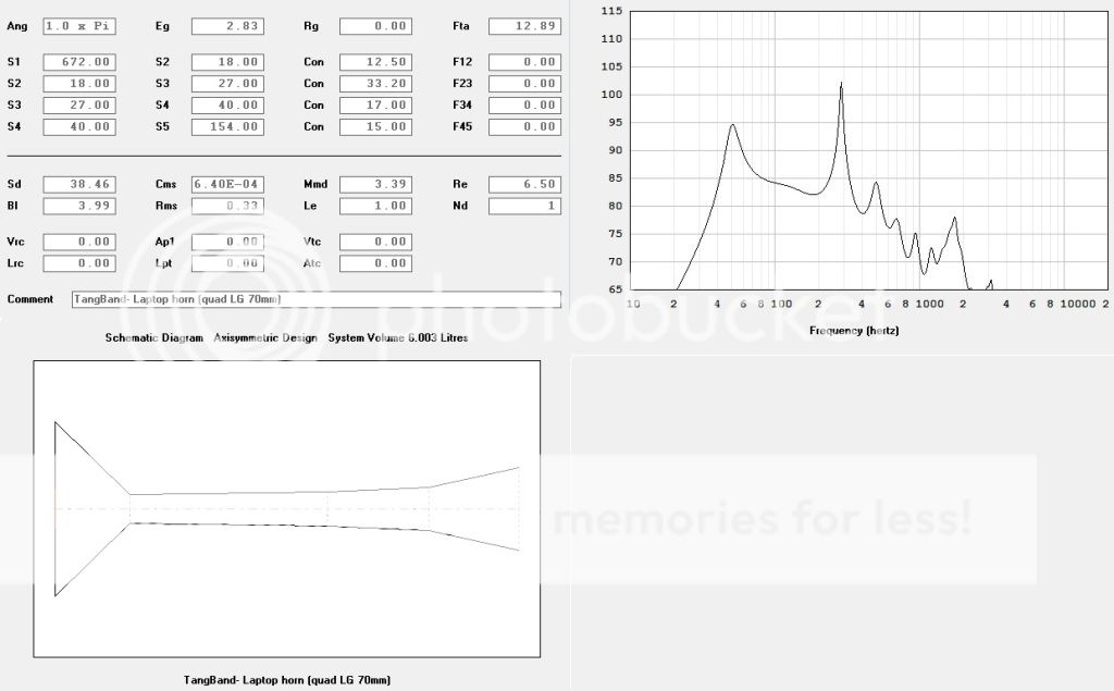
When displaying the horn characteristics, limit your graph range to the frequency range 20 Hz to 1 KHz to view the significant parts. The jaggedness in the higher frequencies can be ignored. It is due to the "perfectness" of the simulation (no losses in the horns, so HF from the back of the driver passes un-attenuated.)
Last edited:
(Missed the edit window time limit...)
I'm not going to add walls etc until I've investigated the problems with the horn bifurcation. I can see the reasoning behind the design - it appears to be intended to work the same as Host Moller's DoppelHorns - but I think equal length horns will perform better.
I'm not going to add walls etc until I've investigated the problems with the horn bifurcation. I can see the reasoning behind the design - it appears to be intended to work the same as Host Moller's DoppelHorns - but I think equal length horns will perform better.
Foam core seems a great idea, but to take this a stage further, has any one tried laminating sheets of corrugated cardboard to a thickness of say 18mm nd using that? I just fitted a flat pack kitchen for someone and ended up with a lot of the stuff, tempted to give it a go.
Foam core seems a great idea, but to take this a stage further, has any one tried laminating sheets of corrugated cardboard to a thickness of say 18mm nd using that? I just fitted a flat pack kitchen for someone and ended up with a lot of the stuff, tempted to give it a go.
Go for it!

 😀 When laminating, you have the possibility of adding a material in between that will damp vibrations (if that is what you want). I have laminated two sheets of foam core with dabs of plumbers putty spread all over and bonding together with hot melt glue (although any glue able to span gap will work - like acrylic caulking). It makes a very nice "dead" sounding panel great for front face if that is what you are looking for - something to sound more like MDF. I suspect cardboard will work fine if laminated. The neat thing with this approach is it is all open for experimentation and in the spirit of DIY fun. We can get serious and try modeling and such but there is something very satisfying with sitting at your kitchen table with a razor and building stuff that actually is very good sounding to the ears without making a lot of sawdust.
The mouth of the "inner" horn is connected to the throats of the "outer" horns at node 7. The "outer" horns are two separate channels of different lengths. There is a significant discontinuity (area change) where the three horns join, which will cause significant reflections at that point. I thought it was poor drawing, but the drawing in the patent shows the same discontinuity so I'll assume for the moment that it is deliberate. There is no "leak" at the join, AkAbak accurately models such joins..
Don Hills,
Thank you for being so helpful with your answers. I have never used Akabak before, is there an instruction manual, tutorial, or thread you can point me to? I don't even have the software installed yet. Complete newbie with Akabak, any more tips you have would be greatly appreciated. It does sound like the model incorporates the bifurcation then. What do you think happens to a brass horn (like a trumpet) that has a bifurcated path and two bells? I think the sounds would oscillate between one and another - rather than divide evenly. It would be interesting if MJK picks up on this and mods his Mathcad sheets to incorporate multiple paths - right now it is strictly one path and you can do things like Planet10 suggested to "fool' it to thinking it is multiple paths like how Sachiko was modeled.
Thanks again.
Regards,
Xrk971
If you bond the laminations together with PVA wood glue or some other wood/construction adhesive, It is going to be impressively strong.
I would suggest paying particular attention to how you bond the edges of the cardboard to whatever you are gluing them to -- as those edges have very little surface area. You might want to use PVA glue as well as hot melt - the hot melt will put it in place, and the PVA will then have time to set properly.
Please report back with any information you have whilst trying your idea!
😀 😀 😀
yes, that was my main reservation in this prospect. Especially using a 6X9, but I thought if i can do it cheap enough, I might at least learn something. so its function over form!
Yes I agree about the beauty of the square design. but I though seeing as ive already violated that with a 6X9 may as well keep going!
But thankyou for giving my drunken idea purpose!
I really think you out to give the rectangle a try. One great reason to do so is the fact that the stock foam core boards from the dollar stores come in a 20 in x 30 in size. Is it sheer serenditpity that it is in the 2:3 aspect ratio? Just scale the drawing to 20 in x 30 in at a reprographics store, align it in such a way to equalize the long and short paths as Dave (Planet10) suggests - there may be something acoustically magical waiting for you. The 6x9 speaker will have a lot of bass, if you happen to have the car audio variety that has coaxial tweeter, even better! I might have to try this myself...😉 The design may have to be modified with a box that is large enough to accommodate the 6x9. You can do this by placing a riser box above the main speaker box hole and have a raised driver section. Otherwise it would have to be scaled much larger to hold 6x9 inside the main cavity. See scaled picture in 2:3 proportions.
Good luck.
Last edited:
The Zen Acousta design might be worth a try in foam core 😀
http://www.diyaudio.com/forums/full-range/224709-zen-acousta-2.html
http://www.diyaudio.com/forums/full-range/224709-zen-acousta-2.html
Just scaling to a rectangle will not work. Don's comments suggest that even the square needs work in terms of smoothing the expansions, stretching in one direction will yield horn paths that actually get smaller in places.
dave
dave
... I have never used Akabak before, is there an instruction manual, tutorial, or thread you can point me to? I don't even have the software installed yet. ...
Read all of this thread:
http://www.diyaudio.com/forums/multi-way/90362-akabak-simulator.html
Note my "AkAbak for the cognitively challenged" posts.
Go here for the software: R&D-Team - Software Development
There's a manual and a set of worked examples included in the package.
... It does sound like the model incorporates the bifurcation then. What do you think happens to a brass horn (like a trumpet) that has a bifurcated path and two bells? ...
I don't know, but it's easy enough to simulate with AkAbak. 🙂
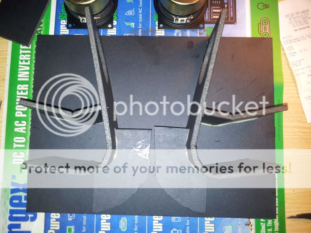
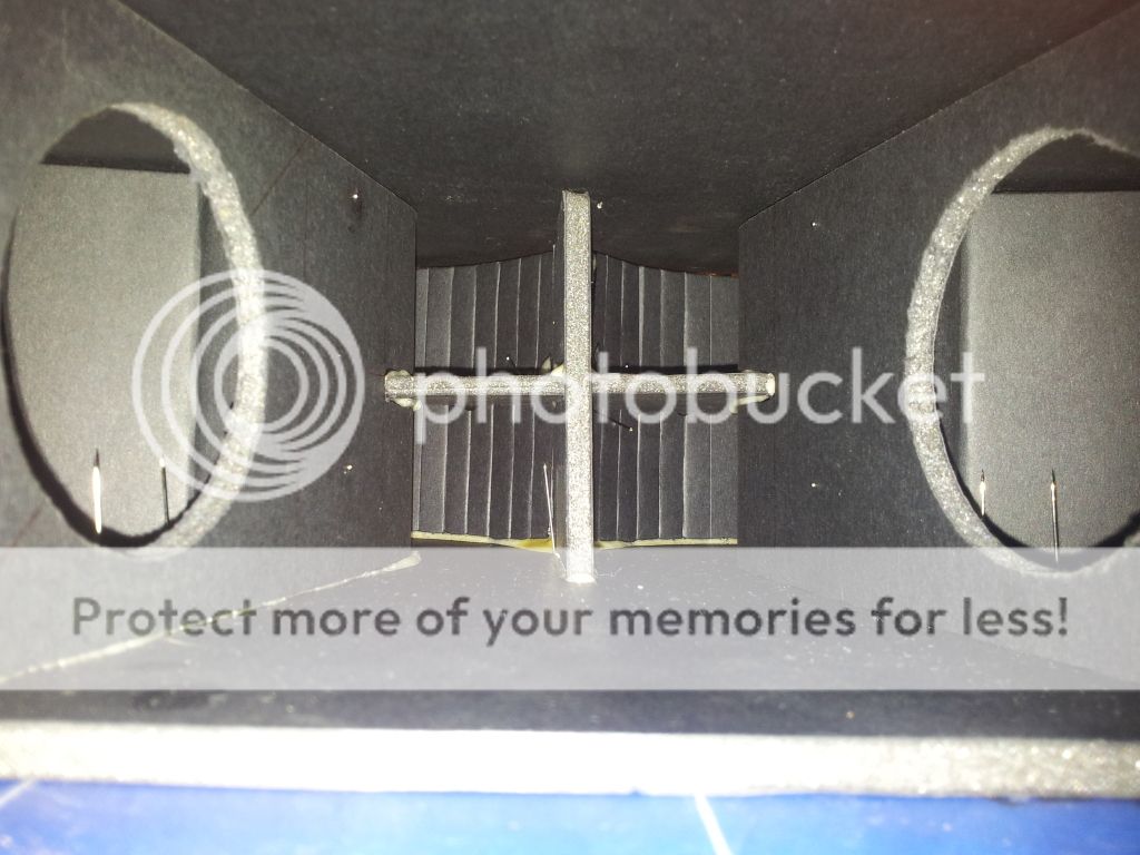
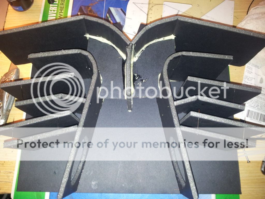
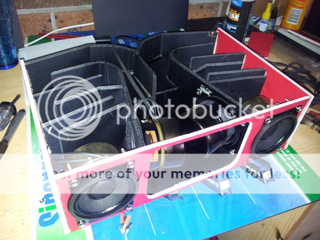
ok, finally able to get online at work with my phone and laptop. heres some pics of my current project, nearly finished too.

- Home
- Loudspeakers
- Full Range
- Foam Core Board Speaker Enclosures?