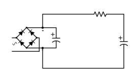
I've read veterans here advising us non experts to think about circuit flow, avoiding sharp corners, and maximising reference to circuit ground. So I'm wondering about the following scenario where one is wanting to add a CRC filter to an existing PCB where there is only connection for one filter capacitor. My gut says that the lower circuit with outboard filter tied in at one place will work because the circuit still sees the whole CRC filter, but that performance will be better if done 'properly' as per the top example where impedance and flow is better. Is that right or am I missing it completely?

Neither, the first capacitor should go directly to the rectifier. From there, bring out the
two +/- connections to the rest of the filter.
Large current pulses go between the rectifier and first capacitor. You don't want to comingle
those pulses with the rest of the filter.
two +/- connections to the rest of the filter.
Large current pulses go between the rectifier and first capacitor. You don't want to comingle
those pulses with the rest of the filter.
Attachments
I'm slightly confused. So my bottom option of post 3 was wrong because it has both caps seeing the rectifer at the same time so there is effectively no "first cap" to take the rectifier current pulses.
Yet, I'm unclear on how the example in post 2 is any better. The classic arrangement would seem to be something closer to this.
...As I said, slightly confused.

Yet, I'm unclear on how the example in post 2 is any better. The classic arrangement would seem to be something closer to this.
...As I said, slightly confused.
The elephant in the room is the ground point for the regulator. The output is a a stable, DC clean with respect to that reference point.
In your schematic, the connection of the regulator reference is somewhere along the supply return line. That is far from optimal.
There are ground currents along that return line and every point on that line has some DC and ripple on it.
The reg reference point should be connected to the very last ground point in the whole setup, and then that will be the ground reference for the load circuitry.
Jan
The rectifier and the first capacitor are the first subcircuit. The remaining parts are the second subcircuit.
You don't want those subcircuits to interact, any more than is unavoidable.
Ground noise, comprised of 120Hz pulses from the ohmic voltage drop due to the rectified current pulses,
is present in the connection between the first capacitor negative terminal, and the rectifier.
This noise must not be coupled into the second subcircuit, or there can be noise in the regulator output.
The way to avoid such coupling is to connect the second capacitor's negative terminal directly
to the first capacitor's negative terminal, but do not connect the second capacitor to the rectifier,
or anywhere else in between the rectifier and the first capacitor.
Connections to "ground" are not arbitrary, and must be done to minimize parasitic effects present
in the circuit, such as the noise from the voltage drop, either on the connecting wires, or on the pcb traces.
Maybe part of the confusion has to do with the fact that in post #1 and post #3 the "bottom examples" are not equivalents of the "top examples". In both "bottom examples" the first resistor and second capacitor get paralleled to the first capacitor and the positive terminal of the bridge rectifier gets connected straight to the third capacitor and regulator (so the resistor is no longer in the path from the positive terminal of the bridge rectifier to the regulator).
Hmm. All right, I'll abandon that. I'll use a rectifier & filter board and attach it to the other power supply board at its filter cap connection.
Thanks for all your input.+
BTW: the sample voltage reg circuit was not a real life plan, just a simple mock up so that we could talk about the rectifier/filter section. So I know the grounding was not best, just lifted out of a datasheet for simplicity of the example.
Thanks for all your input.+
BTW: the sample voltage reg circuit was not a real life plan, just a simple mock up so that we could talk about the rectifier/filter section. So I know the grounding was not best, just lifted out of a datasheet for simplicity of the example.
Maybe this helps showing what I think others in this thread were trying to make clear to you.
In the situation on the left side the red coloured leads will be shared by the first capacitor and the rest of whatever the power supply would be feeding. In the situation on the right there are no leads anymore that are being shared by the first capacitor and the rest (except for the tiny bits of lead in the bridge rectifier itself).
The situation on the right is better than the situation on the left.
I guess that you know the right answer(s) to that so please present it/them here.
I can just describe what I did in my more recent builds.
I have good experiences with connecting earth (coming from a three prong mains connector) to the audio input terminals (there I create a starpoint for practicaly all negative leads; I don't use circuit boards but point-to-point wiring). The audio input terminals are not isolated from the chassis so the chassis is earthed at the audio input terminals.
In the one headphones amp I built I chose to connect earth to the output terminal for the headphones and created a starpoint there because the negative leads of the two channels are coming together there anyway (if than I would choose the input terminals as the place to connect earth, I would create a ground loop).
I think that the way I do this is not according to safety regulations (in some or most countries?). If I'm not mistaken, earth from the three prong mains connector should be connected (bolted) to the chassis, very close to the connector. But this would mean that I have to isolate audio input terminals from the chassis, something that just creates extra work and has disadvantages when dealing with low input signals (phono, mic, guitar).
I am talking about an external PSU, and was thinking you are speaking of 'ground' as circuit common not as chassis ground and therefore potentially floating from the chassis? But in any case you are talking about where the reference(s) or tie-ins to circuit common of the PSU should be, right?Yes, indeed.
Next question is where the ground for the system will be connected.
Jan
Neither, the first capacitor should go directly to the rectifier. From there, bring out the
two +/- connections to the rest of the filter.
Large current pulses go between the rectifier and first capacitor. You don't want to comingle
those pulses with the rest of the filter.
OK, so if they are separate sub-circuits what makes one the 'first' capacitor that handles the large current pulses? Is it just the shorter leads and thus lower resistance?Maybe this helps showing what I think others in this thread were trying to make clear to you.
In the situation on the left side the red coloured leads will be shared by the first capacitor and the rest of whatever the power supply would be feeding. In the situation on the right there are no leads anymore that are being shared by the first capacitor and the rest (except for the tiny bits of lead in the bridge rectifier itself).
The situation on the right is better than the situation on the left.
View attachment 1022789
I've not run into this distinction before as most of the schematics I've seen were more like the one on the left, including Wayne's headphone amp (Whammy).
BTW: my wrestling with Sharedraw resulted in the longer leads and more awkward layout, but was helpful in that it revealed this issue for discussion which I was needing to understand.
Last edited:
Yes. For correct grounding/ground reference it really doesn't matter whether the psu is external or internal, except of course for wire length.I am talking about an external PSU, and was thinking you are speaking of 'ground' as circuit common not as chassis ground and therefore potentially floating from the chassis? But in any case you are talking about where the reference(s) or tie-ins to circuit common of the PSU should be, right?
The issues are the same: trying to get a nice clean ground at the circuit without sharing the wiring with large return currents from the psu caps and load return.
Somewhere above I saw a sim circuit with small resistors in the wiring between the caps to simulate wire resistance.
That's very good, but it should also be done in the ground wiring between cap returns and bridge return.
Those pesky parasitics are everywhere!
Jan
Yes, I’d run the following directly to a circuit common junction at the end:Yes. For correct grounding/ground reference it really doesn't matter whether the psu is external or internal, except of course for wire length.
The issues are the same: trying to get a nice clean ground at the circuit without sharing the wiring with large return currents from the psu caps and load return.
- Neg leg of the filter section
- Adjust leg/circuit of the voltage reg
- Neg leg of any caps associated with or following the voltage regulator
I didn't realise that.Somewhere above I saw a sim circuit with small resistors in the wiring between the caps to simulate wire resistance.
That's very good, but it should also be done in the ground wiring between cap returns and bridge return.
Those pesky parasitics are everywhere!
Yes, lower resistance, including the actual series resistor.OK, so if they are separate sub-circuits what makes one the 'first' capacitor that handles the large current pulses? Is it just the shorter leads and thus lower resistance?
- Home
- Amplifiers
- Power Supplies
- Flow question on PSU filter