Hi,
I doubt Zaph will be after our blood but he was sensible enough
not to post a TL version of the ZD5 where the builders pet
theory was most TLs are too long by about a factor 2.
I think he's sold on the RS180 drivers rather than the DA175.
Does the RS180 fit your updated Thor drivers sims ?
Though the BAMTM is far better than the original choice.
TLv2 looks good and follows MJK's suggestion of
tuning the higher Qts drivers somewhat lower.
🙂/sreten.
That's because it's partially derived from Martin's alignments. Unless a max-flat impedance design is needed, these days I tend to use a hybrid of his & Augspurger's math (certain aspects compliment each other), along with some of my own. Works for me anyway. In this case, Fp is about half an octave below Fs & Vp is kept high.
Will have to check on the RS180, but they look easy enough to work with, plus of course, Zaph's got his ZDT3.5 out, so like these BAMTMs, there's an excellent XO already there.
Not sure about that just being a pet theory -a lot of TLs are arguably too long; either the designer hasn't paid enough attention to the effect of taper (if any), or damping on Fp, or the importance of the total box volume & the requirements of the drivers being used.
All good fun anyway. 🙂
Hi again,
Have cooled on the idea of doing a TL. Can't quite convince myself that I will get good enough results, and not wanting to be dissapointed have continued my research as you have all helped point things out.
Now am set on a course to build an MTM based on Dr. K. build but using the crossover designed for Natalie P design.
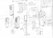
As for the cabinet, I've been doing some drawings. Any feedback much appreciated of course.
Have cooled on the idea of doing a TL. Can't quite convince myself that I will get good enough results, and not wanting to be dissapointed have continued my research as you have all helped point things out.
Now am set on a course to build an MTM based on Dr. K. build but using the crossover designed for Natalie P design.
As for the cabinet, I've been doing some drawings. Any feedback much appreciated of course.
Attachments
Scottmoose said:
Not sure about that just being a pet theory -
All good fun anyway. 🙂
Hi,
I'm pretty sure it was a pet theory backed up with nothing other
than "sounds good to me". The ZD5 TL "design" as I recall was
basically a stuffed floorstanding box with no bottom. It would
have got slaughtered on the Forums if Zaph had posted it.
🙂/sreten.
Greetings,
I am interested in building the BAMTM TLv2 that Scott Moose posted plots. Where does the 86.5
inch long line start from? The middle of the first or second mid-woofer? A drawing would be helpful, nothing fancy. Just to help get things rolling.
Thanks,
Cambe
😎
I am interested in building the BAMTM TLv2 that Scott Moose posted plots. Where does the 86.5
inch long line start from? The middle of the first or second mid-woofer? A drawing would be helpful, nothing fancy. Just to help get things rolling.
Thanks,
Cambe
😎
Neither. It starts at the beginning of the line 😉 i.e the top of the cabinet. Zdriver on the one you refer to (distance from the throat of the line to the centre of the tweeter) is 9.5in. In an MTM configuration, the drivers behave ~ like an oblong source, so you take it from the central point, in this case, the tweeter.
Pity. Why, what are you worried about? There's nothing mysterious about TLs. A decent one is extremely effective -far superior to a de-rigure BR IMNSHO.
Probably, but given that that is exactly what a TL is, or can be, when properly designed (I don't know this particular variation myself), I imagine only by those who know nothing about such cabinets.
Have cooled on the idea of doing a TL. Can't quite convince myself that I will get good enough results.
Pity. Why, what are you worried about? There's nothing mysterious about TLs. A decent one is extremely effective -far superior to a de-rigure BR IMNSHO.
The ZD5 TL "design" as I recall was
basically a stuffed floorstanding box with no bottom. It would
have got slaughtered on the Forums if Zaph had posted it.
Probably, but given that that is exactly what a TL is, or can be, when properly designed (I don't know this particular variation myself), I imagine only by those who know nothing about such cabinets.
Scottmoose said:Neither. It starts at the beginning of the line 😉 i.e the top of the cabinet. Zdriver on the one you refer to (distance from the throat of the line to the centre of the tweeter) is 9.5in. In an MTM configuration, the drivers behave ~ like an oblong source, so you take it from the central point, in this case, the tweeter.
Pity. Why, what are you worried about? There's nothing mysterious about TLs. A decent one is extremely effective -far superior to a de-rigure BR IMNSHO.
Mainly I have found very little real world information about them. It seems that none have been reviewed overly favourably that I have found to fit in my price range. For the time and effort I will put in to building some speakers I think it sagacious to go with something tried and proven. The Dr. K MTM with Nat. P crossover appears to fit this bill from my research. I was initially allured by the exotic TL but have decided to leave it for experimentation later down the line.
Also, I don't understand the logic of how your statement can be true. Why should the 'start of the line' start at the top of the cabinet for one midwoofer driver, but be between the drivers for a dual midwoofer setup? It seems counter intuitive.
As GM said. The 'start of the line' is always at the sealed end of the enclosure, irrespective of the taper of the line, the number of drivers used or where they are positioned along it. Perhaps the attached rough digram will help give you an idea of the layout that would be used for the 2nd & 3rd TL variations I did for Zaphs BAMTM above.
Why aren't there many TLs around? Because it appears not many people know how to design the things properly, or attempt to learn, so they avoid them. It's not been helped by regular comments in magazines, whenever the subject appears, to the effect of 'TL design is a black art', 'TL design is trial and error', 'TL design requires the sacrifice of children under a waning moon to the great brain-sucking god Ooongabba', 'nobody has ever worked out the physics of TLs' etc., etc., etc. None of which are actually true.
Anyway, in reality, if you didn't fancy designing something completely from scratch, you can take most modern slimline BR floorstander designs, for example, and design an excellent TL cabinet for it, assuming it's not doing something unusual with its XO in the lower registers (99.9% don't), and you keep the cabinet the same width as the original to match the BSC built into the XO. A properly designed TL doesn't really require any more experimentation than any other cabinet type once built. With a BR, for e.g., once built, you'd adjust their position in the room, & possibly tweak the internal damping to suit your tastes, right? OTOH, a properly designed TL will need you to adjust their position in the room, and possibly tweak the internal damping. Sound familiar? 😉 Seriously, don't be put off by the fact that the commercials etc., can't be bothered. Compared to the aforementioned modern slimline BR floorstander so fashionable at the moment, a TL will give a much better damped / controlled bass response, usually a cleaner midrange, & also present your amplifier with something approaching an 'ideal' impedance load too (which is where they get their Transmission Line name from).
Attachments
Hi,
I made this.
SpeakerBuilder Passage 2.0
I made this.
SpeakerBuilder Passage 2.0
An externally hosted image should be here but it was not working when we last tested it.
This is my version of Jon Marsh's Modula MTM:
http://farm4.static.flickr.com/3026/2679274911_aef43eb7a8.jpg?v=0
I think you see there are a variety of crossover options when using the RS180's in an MTM arrangement.
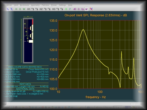
Note the scale of the response plot. Much of the "ripple" has been designed out by using Martin's TL worksheets. Subjectively, this alignment is "fast & tight" as long as there is a moderate amount of room reinforcement of lower bass.
My box alignment requires a large enclosure...I accepted that in pursuit of the "best" I could get out of the pair of mid woofers. It can be scaled back if size is of a concern. You must decide for yourself the important issues with that.
http://farm4.static.flickr.com/3026/2679274911_aef43eb7a8.jpg?v=0
An externally hosted image should be here but it was not working when we last tested it.
I think you see there are a variety of crossover options when using the RS180's in an MTM arrangement.
Note the scale of the response plot. Much of the "ripple" has been designed out by using Martin's TL worksheets. Subjectively, this alignment is "fast & tight" as long as there is a moderate amount of room reinforcement of lower bass.
My box alignment requires a large enclosure...I accepted that in pursuit of the "best" I could get out of the pair of mid woofers. It can be scaled back if size is of a concern. You must decide for yourself the important issues with that.
By the way,
I like the curves you are working with and encourage you to see them through.
The leather baffle can be done...stay with that as well...if you aren't comfortable with gluing the baffle in place, you might find long screws to insert from the back...
I like the curves you are working with and encourage you to see them through.
The leather baffle can be done...stay with that as well...if you aren't comfortable with gluing the baffle in place, you might find long screws to insert from the back...
Hey,
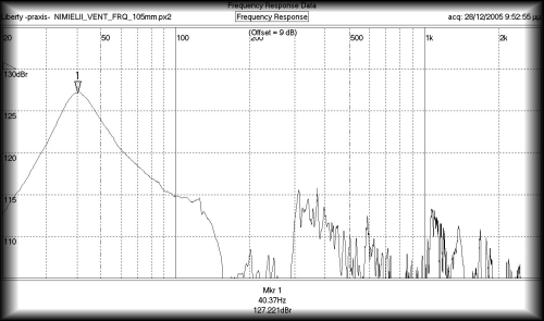
How do you know its fast and tight, from that response graph?
You should look at the stepresponse instead.
Heres a pre-calculator for reflex enclosures
Stepresponse calculator
the graph heres is part of my new software for calculating boxes, that replaces the one skaaninge /audiotechnology uses, that i made for him years back.
Skaaninge SCP
My use of "fast & tight" was subjective...a personal opinion. They were just reviewed by judges and the crowd at diyDayton. So, there may be some other opinions available. 😉
One of the things missing from "reflex" enclosure design is the consideration that can be given to the positioning of all of the elements within the system. The distances between the drivers, enclosure surfaces, port location and length are interrelated. There can be some resonances built in or (better) canceled through their judicious placement.
During the time I spent working with Martin's worksheets, I began to realize this. My sharing of the response graph doesn't back up any claim for "fast & tight". It does show how far the response of a pair of RS180's can go, with very little ripple and a moderate amount of stuffing.
Hi,
Ah, ok. Though you have to add the drivers natural nonlinear response to youre respons calculation.
A greek guy has made simular software to predikt port resonances in refleks systems. Calculated from the placement of drivers and ports in the enclosure.
About center on the page here :
MTZ Lfa software
Okay,here is what I did based on what has been said:
On the original plans of the BAMTM, from the top of the cabinet(internally) to the tweeter is 5.50" minus the .75" MDF thickness plus 5.50" equals 10.25". I didn't get the 9.5". So I am confused. That's why I asked for a sketch of the layout, which Scott you gave, but without the numbers to show how they apply.
😕
Syncroniq said:Hey,
How do you know its fast and tight, from that response graph?
By the Q of its roll off slope above Fb.
GM
Hi,
And the Q is how much in this design? Do you have a groupdelay or stepresponse graph? Can you really know, wether or not you get ringing or not, just by looking at the rolloff? The math is quite complex.
And the Q is how much in this design? Do you have a groupdelay or stepresponse graph? Can you really know, wether or not you get ringing or not, just by looking at the rolloff? The math is quite complex.
Okay,here is what I did based on what has been said:
On the original plans of the BAMTM, from the top of the cabinet(internally) to the tweeter is 5.50" minus the .75" MDF thickness plus 5.50" equals 10.25". I didn't get the 9.5". So I am confused. That's why I asked for a sketch of the layout, which Scott you gave, but without the numbers to show how they apply.
You've lost me. What has the distance of the tweeter from the top of Zaph's original box got to do with the TL I did?
It's quite simple: in the TL, position the centre of the tweeter 9.5in down from the internal top of the enclosure. The upper driver should just squeeze in. I'm sorry I can't provide detailed dimension drawings, but my main PC has been dead since last Wednesday, so I'm on a laptop, and I figured that the dimensions given were easy to convert.
So: assuming 3/4in build material, what you require is a cabinet 44in x 7.5in x 13.25in (internal HxWxD -I've included the thickness of the sloping internal baffle in that depth dimension), using the internal layout of the box I posted above. The sealed end (i.e the bit in front of the sloping baffle) is 10in deep; the open end (i.e. the bit behind the sloping baffle) is 2.5in deep. The centre of the tweeter is mounted 9.5in down from the internal top of the line / cabinet. Stuff the entire cabinet with 0.65lbs ft^3 of hollow-fibre stuffing for the response indicated in the 2nd FR attached to my original post, for the ~ +/- 1db FR ripple, and then adjust the quantity to suit your own taste / requirements from there.
Well, here's one possible MLTL for twin RS180s in an MTM configuration, based on Zaph's measures, & reduced as far as I'm happy. 42in x 7.5in (so existing XOs can be used: if they don't have step compensation built in, don't blame me. I've included a goodly selection of plots on the off-chance) x 11in. Zdriver (tweeter centre) 10.5in, Zvent 38in, vent 2in diameter x 3in long. Line with 1in acoustic fiberglass or stuff 0.53lbs ft^3 from the top 35in down.
Attachments
- Status
- Not open for further replies.
- Home
- Loudspeakers
- Multi-Way
- Floor standing speaker project wanted!