Are you referring to output stage (you mention "plate to plate") here or voltage amplification stage ahead of output ?
In that case plot the loadline as you like it (considering your drive voltage swing, supply voltage, maximum anode dissipation curve and desired operating point with consequent break in loadline when the output switches from class A to B - if you want to operate in class AB in the first place that is) and pick the transformer that suits your choice of loadline.
With tube like ECC99 a very quick look at its curves suggests that you'll be looking at something in excess of 10K anode to anode, provided that there is a single anode per side (so one tube does PP work for one channel; no paralleled devices).
With tube like ECC99 a very quick look at its curves suggests that you'll be looking at something in excess of 10K anode to anode, provided that there is a single anode per side (so one tube does PP work for one channel; no paralleled devices).
OPT, 10k or higher ?
thats not good 😱
foundation for this project was the opposite
paralel two halves of a double triode is not equal to paralel devices ?
LL1620 is a very nice OPT, allows a 11.5k primary impedance, but you can only run 8 or 16 ohm secondary. Would be a great fit for the paralleled ECC99.
Member
Joined 2009
Paid Member
I'm hoping to learn a bit from this thread too...
Is this true only if the triode's are well matched - I mean, if the triode's are not that well matched you need to have individual cathode resistors to ensure current matching between the parallel output tubes ?
(and separate resistors allow heat dissipation to be spread over a larger area)
The cathode resistors in the outputs are also superfluous - bias should be set by applying a voltage to the IT secondary windings.
Is this true only if the triode's are well matched - I mean, if the triode's are not that well matched you need to have individual cathode resistors to ensure current matching between the parallel output tubes ?
(and separate resistors allow heat dissipation to be spread over a larger area)
Did you think about 6N7 tubes? You may get similar result cheaper, with no need for a bias voltage source in output stage.
Wavebourn, 6N7 might be a good suggestion, and worth to remember
but at the momment theres plenty other details to deal with
5687/E182CC, supposed to be similar, low impedance output, more expencive NOS
6C19N looks really interesting
Bigun, we had a visit by Revintage
I reckon he knows his stuff, being a pro, and I trust his judgement
He liked it, and added a few details, yet to be "cleared"
regarding tube matching
I was hoping that to paralel each half of a double triode would help a lot
Until I read about balanced tubes
means that each half of a double triode are carefully matched, or selected
nothings ever perfect
I reckon resitors are there fore stability, with multiple devices
To bias each tube individually seems way too complicated on this level
being a driver tube, I may have been naive to believe it was a low 2300ohm(Ri)
zigzagflux suggested LL1620, a rather big 11k OPT
But could be a good choise as it seem to have lots of other options
Quality iron may cost, but at least they last
Personally I favour easy and cheap tube shift
what I wouldnt like to experience afterwards is a wrong OPT type
btw, any ideas about expected power ?
Attachments

I'm hoping to learn a bit from this thread too...
Is this true only if the triode's are well matched - I mean, if the triode's are not that well matched you need to have individual cathode resistors to ensure current matching between the parallel output tubes ?
(and separate resistors allow heat dissipation to be spread over a larger area)
You are mixing up the setting of the bias voltage with ensuring matched currents through each tube.
I'd suggest biassing the tubes by applying the relevant voltage at the IT secondary winding centre tap. One point, easy to execute, absolute certainty of what bias voltage is applied.
Without getting into a complex servo scheme, there is no way to ensure dynamic matching of the tube currents. Individual resistors MAY allow you to match currents between tubes at idle, but it seems a hell of a lot of trouble to go to to assure yourself of match under only one of an infinite range of operating conditions, and then only on that day. And as you say, they are burning off power for little effect.
first, this seems to have gained more interest than I expected
more than 700 views in about 4days
and theres some very experienced members visiting and helping
I really didnt expect this
and I feel an obligation to follow it through
It also appears like it may be easy to convert to other tubes
that may come later
Yesterday I looked at another IT with 1:2 gain, but with changes
To keep it simple, I like to focus on how THIS design works
And what needs to be done
Zigzag have suggested Interstage and OPT
I think now is time to work on power supply, CCS, etc
no need for a bias voltage source in output stage.
Wavebourn, maybe you like to explain
a few details about how this one works, and about what you had in mind, the differences
and simple please, that would be nice
some have suggested to turn IT around
Dave's version was like that
the opposite way than suggested by manufactor
I wouldnt mind, if its better
maybe anode choke could be used on input/driver tube instead
or resitor would do
But I dont know much about it, really
Attachments
Wavebourn, maybe you like to explain
a few details about how this one works, and about what you had in mind, the differences
and simple please, that would be nice
It is simple: you may compare curves of both tubes. 6N7 was designed especially for output stages of power amps, and it was designed to work with zero volt bias on grids, driven through an interstage transformer.
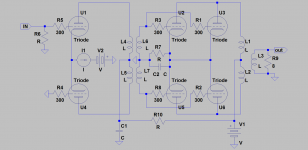
When powered from 300V, with zero grid bias, 8K P-P output transformer, 58V peak-to-peak driving voltage, it outputs 10W. 2 tubes loaded on 4K P-P transformer will give you 20W of max power.
However, when additional grids were added to tubes designers did not use power triodes anymore: using 6V6 and 6L6 tubes they could get rid of costly phase splitting transformers, and less of power was required to drive output toobs.
But if you want a true triode amp with minimum of parts, long forgotten old good workhorses may be used again.
thats interesting wavebourn - I hadn't heard that historical perspective before - thanks!
My pleasure!
ECC99 is really very nice tube, and I would consider it as a waste to use for an output stage. But YMMV, however!
paralel two halves of a double triode is not equal to paralel devices ?
Sure it is, one triode = one device, both devices are in the same bulb ("tube") 🙂 I just couldn't give you numbers without specifying the conditions they apply to and since the curves in datasheets are usually specified for a single device (triode) of a double type such as ECC99 it was natural to give the figure for one half of ECC99 per side, meaning one tube per channel.
If you were to double the the number of devices (both halves of ECC99 driving one side of transformer for example so 2x ECC99 per channel for output duty), the required load impedance would be halved, I figured that was obvious from the formulation of my reply.

I will try to draw another variation of this curcuit
still the same tube, ECC99
other may try 6N6P, or whatever
at the moment its simpler to stick to ECC99
may be presented later today
first small steps
probably several details to correct
someone asked about this previously
I just spotted this line trafo yesterday
and read somewhere else that it may be reversed, giving high gain
next may be PSE version
probably several details to correct
someone asked about this previously
I just spotted this line trafo yesterday
and read somewhere else that it may be reversed, giving high gain
next may be PSE version
Attachments
hey, would be very nice if someone would like to try and explain this thing with biasing the front trafo loading the grids
or would it be better with CCS here
I have seen that done too
btw, a 3 tube version would be possible if each single tube is connected in pushpull
or would it be better with CCS here
I have seen that done too
btw, a 3 tube version would be possible if each single tube is connected in pushpull
Attachments

With tube like ECC99 a very quick look at its curves suggests that you'll be looking at something in excess of 10K anode to anode, provided that there is a single anode per side (so one tube does PP work for one channel; no paralleled devices).
Ok, I understand you better now...5k it is, each half
much better, thanks
🙂
Attachments
- Status
- Not open for further replies.
- Home
- Amplifiers
- Tubes / Valves
- FLEA PPP, all ecc99