This is interesting because I measured a pair of Meyer sound UPJ (10"+horn) yesterday and saw no notch. But maybe I was too far off the hard concrete floor. About 5' or 1.5m
The nearest clear reflection that was visible as at ~2.5m, and it was mild.
If I get the chance, I'll try again at various heights above the floor.
The nearest clear reflection that was visible as at ~2.5m, and it was mild.
If I get the chance, I'll try again at various heights above the floor.
thats because there isn't one, at least not from the floor. The claims of 1/4 wave cancellation are incorrect. Its 1/2 wave path length differences that cause the notch and nothing else.
OK, so you take an omnidirectional sound source generating a 140Hz tone and put it next to a large boundary, two feet away.
What phase relationship is the reflected sound?
What effect do you expect?
This is interesting because I measured a pair of Meyer sound UPJ (10"+horn) yesterday and saw no notch. But maybe I was too far off the hard concrete floor. About 5' or 1.5m
If you're indoors, this would be lost in the room modes. It would be basically be one of them. And you could mitigate it accordingly, with multisubs.
If you're outdoors, you'll see this as a notch at 55Hz. I'd expect it to be between 6dB and 20dB deep. Since you said the floor was concrete, I'd expect it to be a deep notch. Of course, if you use subs, they'll fill this in.
Another related subject - we were talking about the ceiling reflection, and of course there is one in the lower midrange, just like floor bounce. You can smooth it with a couple vertically offset sound sources, dual woofers, flanking subs or a mid and woofer with overlap in this region. But another one of the most offensive reflections to me is what I call ceiling slap. It's much higher in frequency. Sometimes I walk into a room and can hear it right away. Clap my hands and it just rings! I like having relatively narrow vertical beamwidth at high frequencies to counter this. Helps a lot.
Last edited:
Dr. Geddes, what are your thoughts on the dip between 100 and 200 hz Wayne Parham measures even outside. Have you ever measured this floor bounce dip? The explanation of the vertical reflection that somehow messes up things at a couple meters distance seems a bit improbable to me.
If you look at the time domain impulse response, as in Holm, it should be easy to find the culprit by simply windowing at different times etc. If it is not an external reflection, and that's possible as well, then it's in the speaker system itself. I see this all the time - resonances due to the spider, etc. will cause a dip in the radiated response. It would be unusual to see these as low as 100 Hz, though not impossible.
At any rate, I'm not going to debug someone elses measurements other than to point out that a floor bounce dip occurs when there is a path length difference between the direct and reflected sound of 1/2 wavelength. A hard surface will have no phase change due to the reflection. It is completely equvalent to two sources in a free field seperated by twice the distance to the floor.
At any rate, I'm not going to debug someone elses measurements other than to point out that a floor bounce dip occurs when there is a path length difference between the direct and reflected sound of 1/2 wavelength. A hard surface will have no phase change due to the reflection. It is completely equvalent to two sources in a free field seperated by twice the distance to the floor.
Exactly. Which is why there is a large dip when the sound source is 1/4λ from a boundary.
But another one of the most offensive reflections to me is what I call ceiling slap. It's much higher in frequency. Sometimes I walk into a room and can hear it right away. Clap my hands and it just rings! I like having relatively narrow vertical beamwidth at high frequencies to counter this. Helps a lot.
Not surprising really, as ceilings tend to be hard, flat, untreated, and lacking adornments such as book cases, curtains, carpets, and furniture that most of the other room surfaces are typically graced with 😉
As well as that the ceiling is quite well illuminated by the speakers (assuming wide vertical off axis response at high frequencies) since room objects don't generally get in the way.
I sometimes wonder if the ceiling reflection in the treble is connected with the whole "flat power response is not right" discussion that has been running through this thread.
I used to have a very long listening room that was 4m wide by 8m long, and although my normal listening position (for apexed listening) was about 3 metres in front of the speakers it was possible for me to listen much further back, like 5-6 metres seated, or right to the back when standing.
I noticed that by the time I got back to about 5 metres from the speakers (with a 2.4m ceiling) with dome tweeters the apparent image centre increased in height up to a metre or so above the speakers - presumably due to the reflection off the ceiling becoming both closer in angle and time delay to the direct signal the further away you get. At some point it starts to sound like the location of the sound is somewhere between the direct and reflected signal.
When I first changed to ribbon tweeters I was worried about them being too directional vertically, but I now think its a benefit not a drawback. (At least for a ~50mm ribbon that's not too directional) One of the things I immediately noticed is I could sit much further back in the same room and still have the image remain focused and at the same height as the speakers compared to the dome tweeters. There wasn't really much vertical shift, if any, even to nearly the back of the room.
In the dome tweeter case it almost turned into a "wall of sound" at a distance, stretched over a wide vertical angle, and whilst not unpleasant, the image wasn't nearly as well focused as the ribbons.
I put this down to a greatly reduced treble reflection from the ceiling, and ever since then I've been rather fond of the directivity pattern of ribbon tweeters. As long as they're at normal listening ear level and have just wide enough vertical dispersion to account for moderate variations in listening height, the directivity is a plus in my opinion.
Last edited:
gedlee said:It is completely equvalent to two sources in a free field seperated by twice the distance to the floor.
Earl has a point there - the mirror image second driver below the floor that the reflection from the floor represents accounts for traditional floor bounce reflection effects, but not for a notch 1/4 wavelength above the floor as heard at the listening position.Exactly. Which is why there is a large dip when the sound source is 1/4λ from a boundary.
Are we sure that it's not just the effects of the 2nd order floor/ceiling mode receiving a different amount of excitation depending on the height of the driver ?
You say you've measured it outdoors with only the ground present, but where was the microphone ? If it was directly above the speaker then you have a traditional 1/4 wavelength boundary cancellation, but do you see the same notch frequency if the microphone is a couple of metres beside the speaker instead of above it ?
Which is why there is a large dip when the sound source is 1/4λ from a boundary.
Not according to Pythagorus.
Its total path length difference, which depends on the distance to the source as well as the distance to the floor.
Not according to Pythagorus.
Its total path length difference, which depends on the distance to the source as well as the distance to the floor.
There's that, sure. But at these frequencies, the notch from path length delta is smaller than the direct self-interference notch. The largest dip is found at the frequency where the boundary is 1/4λ away. There are higher frequency notches too, both from path length deltas and from odd multiples of 1/4λ (where path self-interference phase difference is a multiple of 180°). But again, the biggest notch is the lowest one, which is usually 6-20dB in depth.
There's that, sure. But at these frequencies, ...
OK, if you say so.🙄
There's that, sure. But at these frequencies, the notch from path length delta is smaller than the direct self-interference notch. The largest dip is found at the frequency where the boundary is 1/4λ away. There are higher frequency notches too, both from path length deltas and from odd multiples of 1/4λ (where path self-interference phase difference is a multiple of 180°). But again, the biggest notch is the lowest one, which is usually 6-20dB in depth.
Wayne, as Earl pointed out cancellation is max at 180° phase shift (1/2 lambda). Of course there is some attenuation at 1/4 lambda but there's something else going on when you see a deep notch at 1/4 lambda but none at 1/2 lambda.
Again, I'll ask this rhetorical question:
When you have a sound source near a large boundary that is 1/4λ away, what phase relationship is the reflected sound when it returns to the source? What is 1/4λ, doubled?
Take an omnidirectional sound source generating a 140Hz tone and put it next to a large boundary, two feet away.
What effect do you expect?
Again, I'll ask this rhetorical question:
When you have a sound source near a large boundary that is 1/4λ away, what phase relationship is the reflected sound when it returns to the source? What is 1/4λ, doubled?
Take an omnidirectional sound source generating a 140Hz tone and put it next to a large boundary, two feet away.
What effect do you expect?
We already discussed that, 1/4 lambda is only true for the front wall because the distance from the speaker to the wall and back to the speaker is 1/2 lambda. But how is this relevant to the floor bounce? We're sitting in front of the speaker not 1/4 lambda in top of the speaker.
That's true, but the radiation is omnidirectional at these low frequencies. The reflected wave partially cancels the source. It's actually pretty good coupling, because the notch is deep.
Wayne, it appears I'm not the only one who doesn't understand. I'm totally on the same page with you when it comes to a boundary at a quarter lambda causing a 180 degree phase difference when the wave returns to its source location. For a rear wall reflection that would cause a dip in the response. But how can a vertical reflection ever reach the listener, who is not on the same vertical axis as the loudspeaker? The floorbounce causes a dip when the pathlength difference between the reflected sound and the direct sound is equal to a half lambda. Maybe you should make a schematic drawing with the sound-rays and specular reflections that you think cause this other dip at the listening position, lower in frequency.
What's happening is the sound energy is actually being partially cancelled at the source. There is still some radiated in other directions, which is why the cancellation isn't complete. But there's enough cancellation that there's a significant notch.
It's kind of like putting two speakers in close proximity, driven in opposite phase. The mutual coupling sets how much sound is radiated into the room, and how much is simply cancelled. Some sound energy will still be radiated into the room, and that will take on all the other effects we've discussed here, room modes, path length delta cancellation, etc. But again, some energy won't radiate into the room because of destructive interference right at the source.
It's kind of like putting two speakers in close proximity, driven in opposite phase. The mutual coupling sets how much sound is radiated into the room, and how much is simply cancelled. Some sound energy will still be radiated into the room, and that will take on all the other effects we've discussed here, room modes, path length delta cancellation, etc. But again, some energy won't radiate into the room because of destructive interference right at the source.
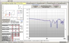
I've tried a few simulations in Room Response Calculator, to examine the predicted difference between a ground plane only, and a theoretical "room" with only a ground plane and ceiling. (By setting coefficients of floor and ceiling to 0.8 and the walls to 0)
I've set up representative values for my room - 2.4 metre ceiling, 4.8m x 3.45m, listener is about 2.5 metres from the speakers and ear height is just over 1 metre. I ran all tests in "Calculate Response 1" mode, which only simulates the left speaker, to avoid any effects caused by the two speakers interacting.
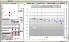
I've chosen 3 woofer heights, 0.9m, 0.6m and 0.4m. In each graph the light red line is the predicted response where only the floor exists - which follows a classic comb filtering shape.
The solid blue line is with both floor and ceiling present, but no walls present. Speaker height was varied to find the worst possible notch between 100-200Hz. Although there is a fairly decent notch at 0.8m I found an even deeper notch at 0.9m, thus its inclusion in the results.
The notch is on the order of 25 dB, and that's with a reflection coefficient of only 0.8 - hopefully typical of a typical wooden floor and suspended ceiling. It goes without saying that the notch is only present when the ceiling is.
For this particular listening position (and without walls present) 0.6m gave the smoothest response, but anything between 0.2m and 0.6m gave a reasonably smooth notch free response between 100-200Hz, as can be seen from the 0.4m response, but with a slight rise in response towards 200-300Hz as you approach the floor.
Of course with a different listening position or the presence of nearby front and side walls, this rosy situation at 0.6m may not be the case - from varying the height and listening position over many different combinations it seems that the lower the speaker is, down to about 0.2m, the "safer" it is with different room combinations and listening positions, but a bit of additional top end roll-off is required for a balanced response through to the midrange.
From this it does seem to me that the interaction between floor and ceiling is the primary cause of a deep notch between 100-200Hz, so I can't explain how it could measure this way outdoors.
I invite anyone who is curious about the results obtained with other variations of woofer height, listening position, presence of walls etc to download the calculator from here:
Room Response Calculator - Reflective Accumulation Simulation Software
I've set up representative values for my room - 2.4 metre ceiling, 4.8m x 3.45m, listener is about 2.5 metres from the speakers and ear height is just over 1 metre. I ran all tests in "Calculate Response 1" mode, which only simulates the left speaker, to avoid any effects caused by the two speakers interacting.
I've chosen 3 woofer heights, 0.9m, 0.6m and 0.4m. In each graph the light red line is the predicted response where only the floor exists - which follows a classic comb filtering shape.
The solid blue line is with both floor and ceiling present, but no walls present. Speaker height was varied to find the worst possible notch between 100-200Hz. Although there is a fairly decent notch at 0.8m I found an even deeper notch at 0.9m, thus its inclusion in the results.
The notch is on the order of 25 dB, and that's with a reflection coefficient of only 0.8 - hopefully typical of a typical wooden floor and suspended ceiling. It goes without saying that the notch is only present when the ceiling is.
For this particular listening position (and without walls present) 0.6m gave the smoothest response, but anything between 0.2m and 0.6m gave a reasonably smooth notch free response between 100-200Hz, as can be seen from the 0.4m response, but with a slight rise in response towards 200-300Hz as you approach the floor.
Of course with a different listening position or the presence of nearby front and side walls, this rosy situation at 0.6m may not be the case - from varying the height and listening position over many different combinations it seems that the lower the speaker is, down to about 0.2m, the "safer" it is with different room combinations and listening positions, but a bit of additional top end roll-off is required for a balanced response through to the midrange.
From this it does seem to me that the interaction between floor and ceiling is the primary cause of a deep notch between 100-200Hz, so I can't explain how it could measure this way outdoors.
I invite anyone who is curious about the results obtained with other variations of woofer height, listening position, presence of walls etc to download the calculator from here:
Room Response Calculator - Reflective Accumulation Simulation Software
Attachments

Last edited:
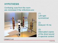
There seems to be some confusion over floor bounce or reflections in general so I've nicked some good diagrams from the web🙄.
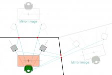
The best way to picture it is as if the walls, floor and ceiling of your room were all mirrors. You would be able to see the speaker in question and multiple reflections above, behind and beside for a speaker near a corner (1 speaker and 7 images). Linkwitz shows it well with a picture of a model speaker in a mirrored corner. The beauty of thinking of it this way is that it makes the path of the sound ray obvious, it simply comes in a straight line from the various image loudspeakers.
Not only do these 8 sources exist, but the opposite wall adds another group. In fact, since sound can bounce back and forth between walls a large number of times, many images would be visible if you looked into the mirrors in any direction (just as you see lots of reflections if you stand between two parallel mirrors.
If we wanted to create a computer model of this we would only have to set up the geometry of the multiple reflections and give them all a driving impulse at the same time, t=0. We would notice 2 things, first the far speakers would have a greatly reduced level simply from the greater distance (1/R loss). Secondly, the model should include absorption loss for every surface that a distant sound ray passes through. If our walls have an alpha of .4 (40% absorption) then this would be compounded by every reflection (or boundary transition, in our model). From these two factors we can probably simplify the model by cutting off images more than 5 to 10 "rooms" away and get nearly the same result.
A second picture attached shows a single speaker in a rectangular room with many image rooms surrounding it. This model alone is enough to calculate the standing waves of the system in the room, at least in that plane. Note that a proper model has to be 3 dimensional with rooms above and below.
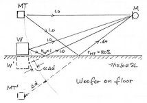
Linkwitz has a nice sketch with a side view only, illustrating a floor bounce. The image system is an equal spacing below the floor that the real speaker is above, but you can see in the drawing that we are nearer the real speaker than to the image speaker. A second woofer on the floor shows that its paths are more equal in distance (so the cancelation null will go higher). This sketch also illustrates why ground plane measurements work. As the listener or microphone gets closer to the floor, the path length to the real speaker and to the image speaker become equal and the first null moves above the audio band.
Finally, it is suggested that the woofer sees its reflection and that the radiated power is modified by the presence of its reflection. My understanding is that that is not the case. The woofer's mechanical impedance is great enough that the reflected sound has no impact. Cancelation notches are totally explained by path differences adding up to 1/2 wavelength delay (reflections off of a hard surface are in phase with the incident wave).
Hope that helps.
David S.
The best way to picture it is as if the walls, floor and ceiling of your room were all mirrors. You would be able to see the speaker in question and multiple reflections above, behind and beside for a speaker near a corner (1 speaker and 7 images). Linkwitz shows it well with a picture of a model speaker in a mirrored corner. The beauty of thinking of it this way is that it makes the path of the sound ray obvious, it simply comes in a straight line from the various image loudspeakers.
Not only do these 8 sources exist, but the opposite wall adds another group. In fact, since sound can bounce back and forth between walls a large number of times, many images would be visible if you looked into the mirrors in any direction (just as you see lots of reflections if you stand between two parallel mirrors.
If we wanted to create a computer model of this we would only have to set up the geometry of the multiple reflections and give them all a driving impulse at the same time, t=0. We would notice 2 things, first the far speakers would have a greatly reduced level simply from the greater distance (1/R loss). Secondly, the model should include absorption loss for every surface that a distant sound ray passes through. If our walls have an alpha of .4 (40% absorption) then this would be compounded by every reflection (or boundary transition, in our model). From these two factors we can probably simplify the model by cutting off images more than 5 to 10 "rooms" away and get nearly the same result.
A second picture attached shows a single speaker in a rectangular room with many image rooms surrounding it. This model alone is enough to calculate the standing waves of the system in the room, at least in that plane. Note that a proper model has to be 3 dimensional with rooms above and below.
Linkwitz has a nice sketch with a side view only, illustrating a floor bounce. The image system is an equal spacing below the floor that the real speaker is above, but you can see in the drawing that we are nearer the real speaker than to the image speaker. A second woofer on the floor shows that its paths are more equal in distance (so the cancelation null will go higher). This sketch also illustrates why ground plane measurements work. As the listener or microphone gets closer to the floor, the path length to the real speaker and to the image speaker become equal and the first null moves above the audio band.
Finally, it is suggested that the woofer sees its reflection and that the radiated power is modified by the presence of its reflection. My understanding is that that is not the case. The woofer's mechanical impedance is great enough that the reflected sound has no impact. Cancelation notches are totally explained by path differences adding up to 1/2 wavelength delay (reflections off of a hard surface are in phase with the incident wave).
Hope that helps.
David S.
Attachments

Finally, it is suggested that the woofer sees its reflection and that the radiated power is modified by the presence of its reflection. My understanding is that that is not the case. The woofer's mechanical impedance is great enough that the reflected sound has no impact. Cancelation notches are totally explained by path differences adding up to 1/2 wavelength delay (reflections off of a hard surface are in phase with the incident wave).
David S.
Completely correct and exactly what I said before.
- Status
- Not open for further replies.
- Home
- Loudspeakers
- Multi-Way
- 'Flat' is not correct for a stereo system ?