Figure 1,2, and 4 are incorrect.
1,2, the field require a FEA to show the correct field distribution at a specific frequency.
In 4, you are assuming conductivity layer to layer, but layers are insulated.
Jn
In FIG.4, I was following the suggestion of the article in post #39 (page 4):
http://ridleyengineering.com/images/phocadownload/13%20proximity%20loss.pdf
The windings are assumed to be a continuous uniform cross-section of copper, as would be obtained with a flat foil. (In many designs, this layer may be formed with individual wires, and these must be approximated to a foil sheet, a step outside the scope of this article.)
FEA (finite element analysis) is beyond my capability, never used it in magnetics.
But fortunately someone has done it before:
Evaluate Your 3D Inductor Design with COMSOL Multiphysics | COMSOL Blog
In the above link, its first figure might be what you are talking about, those magnetic arrows are shooting everywhere between the inductor body.
Maybe I should narrow down my previous description in #39 as following:
The external summed-up solenoidal magnetic fields of an inductor can never penetrate its top and bottom copper surface.
And the author has analyzed a three-turn edgewise inductor, from the resultant figure of current density we can learn several things. (FIG.5 attached below, copyright highlighted)
If we look closely at FIG.5 below, we can find the currents of an edgewise inductor at high frequency are pulled to the inner and the outer sides, and the top turn has a red (high density) area at its outer and inner top corners, the bottom turn has a red (high density) area at it outer and inner bottom corners, while the middle turn does not have any red area, currents are drawn to the sides by skin effect, and slightly drawn to the corners at the middle turn.
Looks like it fits the description of FIG.1 & 3 in my post #35.
I think at the middle turn of FIG.5, the proximity effect from its adjacent top and bottom turns are mostly canceled out by each other (as suggested in FIG.1 #35). Generally speaking, only the very first top and bottom turns suffer severely from the proximity effect.
The edgewise inductor of FIG.5 is thicker than a foil, so the middle-turn cancellation of proximity effect is not perfect, but since the foil in a flat foil coil is much thinner, I believe the cancellation will be better.
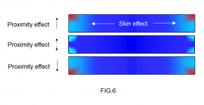
I have drawn the cross section of the FIG.5 edgewise inductor as FIG.6 below, a three-turn/layer stacked structure is shown.
The current distribution of FIG.5 are copied to FIG.6 and explained.
From FIG.5, skin effect is the major effect of an edgewise inductor at high frequency, and proximity effect can be canceled out in the middle turns. We can anticipate the same would happen in a flat foil coil.
Attachments

Your first link is good. However, they erred in the first page..""a large diameter wire has a lower self inductance than a smaller wire.""
No. A cylindrical conductor at DC has 15 nH per foot independent of diameter.
Their discussion on proximity effect is quite good.
It is important to understand the difference between an air core inductor and one with a magnetic focusing structure. Your two pics at the end of your post are with ferrite. It changes the field map.
Sullivan at Dartmouth did a lot of work with gapped ferrite, and it is the gap that causes lots of proximity losses, due to fringe fields.
I like your efforts, thank you. If it were easy, anybody could do it..
Jn
Jn, thank you.
I learned a lot through discussions with you. Your valuable insights have helped a lot.
I never thought of the multi-layers could cause such a big loss.
The one-layer feature of a flat foil coil could be its major difference with other inductors.
And maybe someday someone can use FEA to demonstrate the polarity effect of an inductor.🙂
If this topic were easy, anybody would know it..
There is no polarity effect.
There are however, slew rate effects.
Jn
There is no polarity effect.
There are however, slew rate effects.
Jn
If this topic were easy, anybody would know it..
There is no polarity effect.
There are however, slew rate effects.
Jn
Will you share more with us about slew rate effect? Thanks!