Dear all,
I would like to introduce to you a new type of inductor - the Flat Foil inductor.
Maybe its concept is not so new, but currently it's not available on the market. Though some small flat inductors made of thick copper wires are available (i.e. edgewise inductors), but none of them are made of thin copper foils as this one.
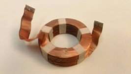
Please refer to the picture of its first hand-made sample, unlike the currently available spiral foil inductors, though the new coil is also made of foils, but the copper foils are in flat (horizontal) directions and folded up to make the coil loops.
Spec of the sample:
inner diameter = 42mm
outer diameter = 66mm
copper foil thickness = 100um width = 12mm
layers N = 93
inductance = 453uH @ 100Hz (ACR=0.3ohm)
inductance = 375uH @ 1kHz (ACR=1.462ohm)
DCR = 0.3ohm
I will briefly describe its advantages as following:
1. Full symmetric structure
- unlike the spiral foil coils which is not symmetric in structure (inner side and outer side), Flat Foil inductors are fully symmetric.
2. No polarity issue
- unlike the spiral foil coils which inherently have polarity issue, full symmetric structure guarantees no polarity.
3. Least vibration
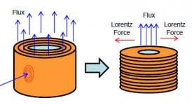
- Flat foils have the least vibration because the flat foil direction is parallel to the Lorentz force, while the spiral foil coils are perpendicular to the Lorentz force and could vibrate easily.
4. Better heat dissipation
- Flat foils conduct the core heat from its center to the outer side, each layer is a heat sink for the core, core heat is evenly dissipated.
5. Least heat expansion deformation
- unlike the spiral foil coils, heat expansion will not cause deformation of the coil.
6. Each layer has the same inductance
- while each layer of the spiral foil coils has different diameter and therefore different inductance for each layer.
7. Less leakage between layers
- while the spiral foil coils have greater leakage flux between layer gaps.
8. Least Eddy current, least mutual inductance
- while the spiral foil coils will induce larger Eddy current when an external vertical magnetic flux penetrates its foil surface. Flat Foil coils have the least mutual inductance because its foil surface is parallel to the external vertical magnetic flux, and therefore the least eddy current.
I am comparing the Flat foil coils with spiral foil coils only, but I think it's pretty much the same when comparing to the wire wound coils.
What do you think about this type of inductors, would it be better when used in the crossover?
Your comments are welcome and will be highly appreciated!
Thanks in advance.
I would like to introduce to you a new type of inductor - the Flat Foil inductor.
Maybe its concept is not so new, but currently it's not available on the market. Though some small flat inductors made of thick copper wires are available (i.e. edgewise inductors), but none of them are made of thin copper foils as this one.
Please refer to the picture of its first hand-made sample, unlike the currently available spiral foil inductors, though the new coil is also made of foils, but the copper foils are in flat (horizontal) directions and folded up to make the coil loops.
Spec of the sample:
inner diameter = 42mm
outer diameter = 66mm
copper foil thickness = 100um width = 12mm
layers N = 93
inductance = 453uH @ 100Hz (ACR=0.3ohm)
inductance = 375uH @ 1kHz (ACR=1.462ohm)
DCR = 0.3ohm
I will briefly describe its advantages as following:
1. Full symmetric structure
- unlike the spiral foil coils which is not symmetric in structure (inner side and outer side), Flat Foil inductors are fully symmetric.
2. No polarity issue
- unlike the spiral foil coils which inherently have polarity issue, full symmetric structure guarantees no polarity.
3. Least vibration
- Flat foils have the least vibration because the flat foil direction is parallel to the Lorentz force, while the spiral foil coils are perpendicular to the Lorentz force and could vibrate easily.
4. Better heat dissipation
- Flat foils conduct the core heat from its center to the outer side, each layer is a heat sink for the core, core heat is evenly dissipated.
5. Least heat expansion deformation
- unlike the spiral foil coils, heat expansion will not cause deformation of the coil.
6. Each layer has the same inductance
- while each layer of the spiral foil coils has different diameter and therefore different inductance for each layer.
7. Less leakage between layers
- while the spiral foil coils have greater leakage flux between layer gaps.
8. Least Eddy current, least mutual inductance
- while the spiral foil coils will induce larger Eddy current when an external vertical magnetic flux penetrates its foil surface. Flat Foil coils have the least mutual inductance because its foil surface is parallel to the external vertical magnetic flux, and therefore the least eddy current.
I am comparing the Flat foil coils with spiral foil coils only, but I think it's pretty much the same when comparing to the wire wound coils.
What do you think about this type of inductors, would it be better when used in the crossover?
Your comments are welcome and will be highly appreciated!
Thanks in advance.
Attachments
Last edited:
I'm a little confused over what this offers compared to a Goertz foil inductor?
Goertz foil inductor's foils are vertically and spirally wound, so I called them spiral foil coils, this new one has foils horizontally layered.
In the figure the left one is spiral foil coil, and the right is flat foil coil.
Attachments
Available, air core or ferrite:Dear all,
I would like to introduce to you a new type of inductor - the Flat Foil inductor.
Maybe its concept is not so new, but currently it's not available on the market.
https://uk.farnell.com/coilcraft/2014vs-251meb/inductor-0-257uh-230mhz-20-smd/dp/2343778
https://uk.farnell.com/wurth-elektronik/7443633300/inductor-33uh-15-12a-hcf-2013/dp/1869767
It sounds like quite a good idea if you know of a companion product made from solid copper bar by a friendly company that will let you have the turnings.
Commercially foil inductors are low values that can be created within the tracks of PCBs in VHF radios and mobile phones.
Commercially foil inductors are low values that can be created within the tracks of PCBs in VHF radios and mobile phones.
Last edited:
I meant more parametrically.
Sorry I got you wrong. And yes, parametrical comparision is not yet performed and probably hard to tell the difference.
For example, vibration, heat deformation, and polarity.
One thing I know is the effect of skin effect, I will talk about it later.
Mark,
Your links are edgewise coils made of thick copper wires with small inductance values. Why they have to use thick copper wires? Because they are edgewise coils, copper wires have to be thick enough to be turned by the edge.
The edgewise coils will become vary thick if you need 100 turns for crossover inductors.
And if you want the same conducting surface as a 100um flat foil coil, it will grow even larger.
I forget to post the length of the sample flat coil, it's 17mm (L) for 93 turns, and in theory it should be 14mm because each layer including isolation is 150um thick.
It sounds like quite a good idea if you know of a companion product made from solid copper bar by a friendly company that will let you have the turnings.
Commercially foil inductors are low values that can be created within the tracks of PCBs in VHF radios and mobile phones.
The sample flat foil coil was not made by turning a solid copper bar, but by folding a 100um copper foil.
The manufacturing process is new and currently there is no commercial machines or any friendly companies available to manufacture it.
How to mass produce it is a problem to be solved.
DCR is not the only factor in inductor design but also capacitance.
And lowest capacitance design for inductors is the HoneyComb design
Wow, that's an interesting design.
About capacitance of an inductor, in my opinion, it is related to the adjacent layers. Foil inductors have larger area between adjacent layers to create stray capacitance, but also foil inductors have the lowest voltage & phase difference between its adjacent layers, because the layers of foil coils are all well arranged in good order, a layer's adjacent layer is the next turn.
While wire wound coils have higher voltage and phase differences between its adjacent layers, its first layer might be just the neighbor of its last layer, and the voltage and phase difference between layers are at its maximum, which will worsen the effect of stray capacitance (higher voltage & phase difference results in higher coupled signal). And the interference (coupled signal between layers) could be in chaos as signals goes by.
Instead, foil coils has the minimum voltage and phase difference between its adjacent layers, and the interference is in relatively simple order.
My point is, the effect of stray capacitance is probably not as bad as one think for a foil coil.
For example, a 20-turn wire wound coil with 10 turns/layer and 2 layers, the last turn is adjacent to and on top of the first turn, if a 100 Volt signal is applied, you need an isolation that can bear 100 volts for these two adjacent turns, signal coupling is resulted from the 100 volts difference.
But for a foil coil, 100 volts are evenly distributed between its 20 layers, it's only 5 volts difference between layers.
Have you tried to turn copper in a lathe? Its too soft to machine. And turnings are mainly chips, not ribbons anyway.
I would imagine whatever thickness of flat copper you just need to roller it to a wedge profile to get the curve, copper is extremely ductile. Goertz configuration will always be simpler to manufacture though and thus will be cheaper.
I think the Goertz winding doesn't suffer from the skin effect so badly - with edgewise the current can be forced to the edges, ie the width of the foil is the relevant dimension, whereas for Goertz its the thickness of the foil. As the skin depth in copper is 2mm at 1kHz, its a big deal.
Have you tried to turn copper in a lathe? Its too soft to machine. And turnings are mainly chips, not ribbons anyway.
I would imagine whatever thickness of flat copper you just need to roller it to a wedge profile to get the curve, copper is extremely ductile. Goertz configuration will always be simpler to manufacture though and thus will be cheaper.
I think the Goertz winding doesn't suffer from the skin effect so badly - with edgewise the current can be forced to the edges, ie the width of the foil is the relevant dimension, whereas for Goertz its the thickness of the foil. As the skin depth in copper is 2mm at 1kHz, its a big deal.
I am impressed that you can foresee the skin effect issue.
Yes, skin effect not only force the high frequency current to flow at the surface of the copper foil, but also force the high frequency current to flow near the inner side of the flat copper foil (radially), causing the effective radius of the inductor to decrease.
As measured from the sample flat foil coil, at low frequency the effective diameter of the inductor is its average diameter, i.e. (66+42)/2=54mm, but at high frequency the effective diameter will decrease near to the inner diameter, i.e. 42mm.
So the inductance at 100Hz is 453uH while at 100KHz it's 357uH, nearly 78% (42mm/54mm=0.77). By the way, it is interesting when the skin effect is causing the AC resistance to increase and at the same time the inductance to decrease, will the decrease in inductance (impedance) somehow provide a compensate to the increase of resistance?
You can calculate the flat foil coil inductance with this link and get a pretty close result. (please use these parameters: 93-53-12-1 & 93-46-12-1)
https://www.eeweb.com/tools/coil-inductance
And about manufacturing, after paste both sides of the copper foil with BOPP isolation films, I then use a die-cut mold to cut the copper foil into the shape I need, and then manually fold it up, a lot of man-hour is required.
This design must surely have high capacitance.? What is the inductor's resonant frequency?
Please give me some time to measure the resonant frequency.
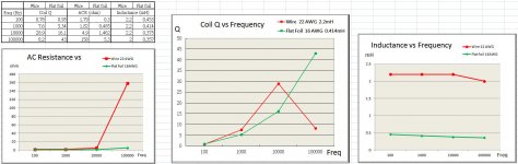
But I have measured some data with a DE-5000 LCR meter for your reference. (Four measurement points, 100Hz, 1KHz, 10KHz & 100KHz)
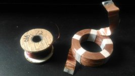
I used a wire wound inductor (0.65mm, 22AWG wire, 2.2mH) to compare with the sample flat foil coil.
The wire wound inductor is actually some copper wires I bought from a vendor, and it comes as it is, randomly wound on a wooden bobbin. Wire wound coils are really easy to make, but they have their problems.
Summary of the result:
1. Wire wound coil's AC resistance increases dramatically at high frequency due to skin effect.
2. The Q factor of the wire wound coil has a peak near 1KHz (might be related to the skin effect), while the flat foil coil acts more like an ideal inductor.
3. The inductance of flat foil coil decrease by frequency, the decreasing rate is related to the ratio of the inner and outer diameter of the flat foil coil.
4. If there is a Q-factor peak for the flat foil coil, it could be at over 100KHz, say about at MHz range. Can we estimate the resonant frequency is also at MHz range?
5. For the flat foil coil, inductance decreases as AC resistance increases. A quite interesting compensation between these two.
Attachments
You are probably right the capacitance is not high enough to affect audio frequencies. I like your coil design, espescially the constant diameter though I am not sure if that really matter at audio frequencies either...
But this design and the Gortz or what its called cannot be used as output filter on class-D amplifiers. For speaker xo it must be very good.
But I would like to see a comparison with a same inductance of different coils. Your posted test is with a coil having 6x the inductance.
But this design and the Gortz or what its called cannot be used as output filter on class-D amplifiers. For speaker xo it must be very good.
But I would like to see a comparison with a same inductance of different coils. Your posted test is with a coil having 6x the inductance.
You are probably right the capacitance is not high enough to affect audio frequencies. I like your coil design, espescially the constant diameter though I am not sure if that really matter at audio frequencies either...
But this design and the Gortz or what its called cannot be used as output filter on class-D amplifiers. For speaker xo it must be very good.
But I would like to see a comparison with a same inductance of different coils. Your posted test is with a coil having 6x the inductance.
Thank you for telling me that you like the design.
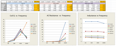
A correction first, the wire wound coil has a Q-factor peak at around 10K~100KHz, not 1KHz (mistaken in previous post).
I have unwinded the wire coil and got four more sets of data with different inductance for your reference, please refer to the figures below.
I am not sure about the requirement of a class-D amplifier, but it seems that some filter designs for class-D also use edgewise inductors. Comparing to the edgewise coils, the folding flat foil coils are relatively thin (for instance, 50um per layer is possible), a more than 50% reduction in coil height could be possible.
And there are a lot of 400Hz aircraft transformers using spiral foil coils for better high-frequency efficiency. Aircraft use 400Hz (not 60Hz) as the frequency for their onboard power transformers because higher frequency results in smaller form factor and lighter weight. In my opinion, flat foil coils could be better than the spiral foil coils for these 400Hz transformers, at least flat foil coils have a better heat dissipation capability for the core. But again, the hard-to-manufacture issue must be cleared first.
Attachments
This design must surely have high capacitance.? What is the inductor's resonant frequency?
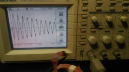
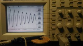
Here comes the resonant frequency.
For the Flat foil coil 414uH resonant at 2MHz
For the Wire-wound coil 443uH resonant at 1.364MHz
I used a TDS 220 oscilloscope's probe calibration output (square wave 5Vp-p @1KHz), with a 1M ohm resistor connected in series with the coils and measured the self-resonant waveform.
The results seems pretty good for the relatively large flat foil coil, and I think its resonant sine wave has a better shape than the wire-wound coil (less distortion and about 4 times of amplitude). But it might be unfair because the wire-wound coil was randomly wound on the bobbin.
Attachments
- Status
- This old topic is closed. If you want to reopen this topic, contact a moderator using the "Report Post" button.
- Home
- Design & Build
- Parts
- Flat Foil Coil - Introduction