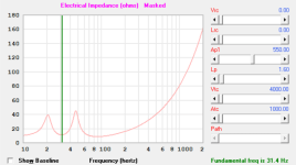
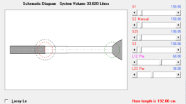
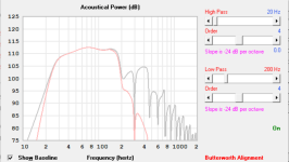
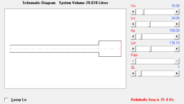
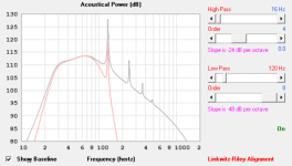
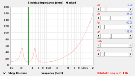
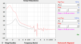
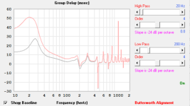
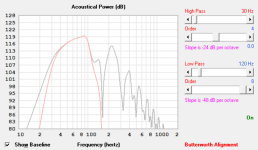
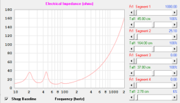
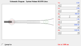
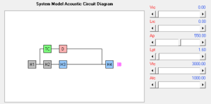
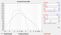
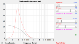
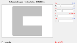
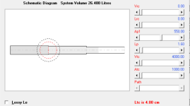
Please see this attempt to add that cosmetic exit flare. I have switched to the TH model Driver entry is though the side of that flare and driver is reversedOver damped response that the room, VC heating will move it towards flat in-room and spikes are vent pipe harmonics comb filtering with the driver's output and AFAIK the only way to deal with them is by 'critically' damping the vent.
The back chamber has fill that brings down the spikes, and the exit has some fill that rounds over the remnants of the spikes. Adding the system low and high pass filters gets rd of these products (artefacts)
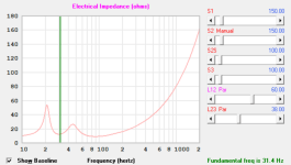
Something is weird, though. The impedance twin peaks are no longer symmetrical, but the system retains the Fb=Fs 31.4Hz. This maybe due to adjusting segment lengths to compensate for the exit flare and fill for dampening. Not sure what's going on with the impedance even though It's tuned at Fs
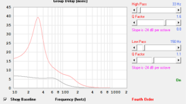
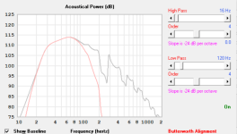
That last pic is some 'fourth order' filter thing that I don't understand, but the response looks good to just get louder. I wonder if my DSP unit supports this
Damping/stuffing will lower impedance peak(s), especially vent damping (making it more aperiodic) as it moves it back towards sealed.
Just what it looks like, a 4th order low pass electrical filter + any XO to the rest of the speaker system.
No clue about DSP options.
Just what it looks like, a 4th order low pass electrical filter + any XO to the rest of the speaker system.
No clue about DSP options.
These below are the basic BR and TL that I am trying to give a cosmetic scoop look without damaging response and keeping the driver reversed for another cosmetic effect. It's not critical to achieve cosmetic effect but very desired
Guys
Would you be able to point out these effects on a graph? Not knowing what such products look like on the screen is debilitating when trying to fathom what you folks are saying
Please help understand what those peaky dip things are in these example pics below, and are they a concern?
Is this the good kind of transient response and roll offs?
Fill dampening to reduce the peaks?
I hope to get at least one box ready and tested for use by August so as not to miss an opportunity to hear it in use in the professional conditions of Brolga theatre, which is our performance arts theatre for the Fraser Coast. It's a rare opportunity to observe a bit of DIY gear in such an environment. Please help understand if these model responses are concerning and understand what needs cleaning up
My basic BR with Vb=Vas and FB=Fs. This what I have been trying to give a cosmetic very large flare exit to, and the basis for the original post in this thread. This is unfilled, unmasked, unfiltered and without Eq. The BR sim gives this note in red, which I don't understand
View attachment 1332045
View attachment 1332021
View attachment 1332044
My basic TL, 3 stepped segments, S1=150x65mm, S2=100x65mm, S3=80x65mm, Vtc=4L. I am really attracted to the TL idea as a crazy tiny labyrinth like this with a huge driver sticking out of it would be cool, and I would build this over the BR if this can be a legit candidate. I'll upload full construction and model input data and methods as a DIY musical multi instrument amplifier to share back everything I have learned from you guys to make a better cab
View attachment 1332027
View attachment 1332043
Please see this attempt to add that cosmetic exit flare. I have switched to the TH model Driver entry is though the side of that flare and driver is reversed
The back chamber has fill that brings down the spikes, and the exit has some fill that rounds over the remnants of the spikes. Adding the system low and high pass filters gets rd of these products (artefacts)
Something is weird, though. The impedance twin peaks are no longer symmetrical, but the system retains the Fb=Fs 31.4Hz. This maybe due to adjusting segment lengths to compensate for the exit flare and fill for dampening. Not sure what's going on with the impedance even though It's tuned at Fs
That last pic is some 'fourth order' filter thing that I don't understand, but the response looks good to just get louder. I wonder if my DSP unit supports this
View attachment 1332055
View attachment 1332059
View attachment 1332060
View attachment 1332062
View attachment 1332063
View attachment 1332067
I sense that I am still not getting it, and these latest iterations show a poor subwoofer. I simmed the DS18 recommended ported box, and it looks much like the rising low end response much like my sims that Whitedragon commented on. To me, my most current sims for BR, TL and tapped TL look much better than the stock DS18 box
The best way for me to build context is by listening and a recognised design as a control cab would be handy to A/B test and hear for myself to see how good or bad these TL subs are
Any recommendations for any Pro sub designs using a 12" driver to compare extension, clarity, musicality and output in A/B listening? Which ones can output a good bass dominant bassline?
@weltersys. Art, do you have a 12" design (maybe I buy the required driver locally or eBay) that would make a good control box for evaluating my ZXI12.4D based subs?
I came across this very compact 12" scoop design. Proportions look pleasing, but I couldn't find any performance details on it. Does anyone know this design? Making something like this that can do low bass with my driver would be brilliant for ambience aesthetics. I would love to design along those lines but aiming for Fb=Fs 31.4Hz
https://www.diyaudio.com/community/...3607236777_6395681562139548438_n-jpg.1143540/
Is this a good or bad thing? I can't work out if the asymmetrical twin peaks due to dampening means a driver not happy on its suspension, referring to Whitedragon's comments on the impedance peaks earlier in the threadDamping/stuffing will lower impedance peak(s), especially vent damping (making it more aperiodic) as it moves it back towards sealed.
No, I have not designed or built anything for a driver like the ZXI12.4D.Art, do you have a 12" design (maybe I buy the required driver locally or eBay) that would make a good control box for evaluating my ZXI12.4D based subs?
You can evaluate any box by measuring and listening to it.
You can compare other drivers to the ZXI12.4D in Hornresp.
The back horn length is only a little more than a meter long, 1/4 wave length puts it's low corner around 67Hz.I came across this very compact 12" scoop design. Proportions look pleasing, but I couldn't find any performance details on it. Does anyone know this design?
It will have the usual BLH upper response dip due to the front and rear output being out of phase.
No, I have the ones designed for the ZXI12.4D. i am asking if you have a 12" design that can be used as a workshop reference for comparative listening testsNo, I have not designed or built anything for a driver like the ZXI12.4D.
Ok cool. I think a higher end 12" HT design might serve such purpose. A known and recognised designI have not built a flat response single 12" design with an Fb as low as what you are looking at.
Again, depends on the performance needs of the app, though WRT to the driver's construction at rated power it in theory just means the driver is presenting a balanced acoustical load when tuned to Fs in a typical BR alignment, though the pioneers concluded it ideally needs to be raised in a sealed box to 1.56x Fs to acoustically protect it, max out its usable peak eff., best transient response, etc., ergo choose a driver based on needing an Fs/1.414, historically the prosound app's choice and last I checked (years ago now) was still used for Eminence's box alignment recommendations.Is this a good or bad thing? I can't work out if the asymmetrical twin peaks due to dampening means a driver not happy on its suspension, referring to Whitedragon's comments on the impedance peaks earlier in the thread
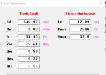
That said, the driver's published specs are a bunch of 'floobie dust' with the 'best' ones (0.53 Qts, forget worst = 2.04 Qts or even its 1.08 mean) yielding a ~120 dB/m/~25 - 90 Hz in a quickie sim based on a 95.52 L tapped pipe (TP)/2 kW/23.9 mm Xmax (no listing, so YMMV)
Strongly recommend measuring this brand/these drivers before wasting anymore time on them beyond as a learning set of specs.
Please Export/Import/attach your HR files for us to DL if wanting me to critique.........
Attachments
Strongly recommend measuring this brand/these drivers
Yes the drivers need to be measured. But a DATS device costs about $300 here, and that almost another driver that could be had. I have ARTA and I think this can be done with it, but I haven't used the program yet as the computer is installed in an area not conductive to such use. I think I will order a refurbished laptop today and let's get these things measured
GM, totally respect the way you conduct yourself online. You are a true GM as in Gentleman or Great Man but on this I have to disagree with you as I take a different view of thingswasting anymore time on them beyond as a learning set of specs
None of this is a waste and I don't mean the awesome educational ride The Fb is a physical property of the box and the only implications for the driver is that it has to suit the box. Let's consider the basic reason for this custom sound system
The greatest constraint is the cab size. There are no existing designs that meet the size/extension+output SOR. Physical size constraints for the 2.1 channels instrument amplifier using one of these cabs for low end reinforcements are;
Height 800mm
Depth 340mm
Width 300mm
1x ZXI12.4D
1 pair PRO-ZT69 racers
3400w of amp modules
DSP + tube based analog front end
A smaller box that that would be even better, but that's the practical small sizes keeping the massive ports in mind and not invoking sealed or PR systems. There is some cm leeway for the width, but only reserved for accommodating the racers
A 31.4Hz Fb tuned BR, TL and tapped TL that fits in that constraints are the largest boxes that I can live with. The 12" ZR and ZXI, the 10" GEN-X as well as multiple Logitech 7" and a Logitech 10" drivers are on hand to try out
I would implement the construction in a manner where any segment length and Sd can be interfered with during initial testing and locked in for final assembly. In other words, the box can be easily detuned higher to suit other drivers in my collection or that can sourced from here
So this effort is very productive time spent in hopes of starting with very good prototyping cabs built to the constraint maximums. And let's not forget the much louder 2.0 section drivers that seem very capable down to 70Hz and will take over from the sub at a variable point or combine over an overlap. A reason to explore the TTL version as that shows flattish up to 200Hz
Taking this into consideration, to work out a likely driver with a lot of hands on, I do really hope that my three basic BR. TL and TTL designs can get some thumbs up as worthy prototyping candidates. I also would really like to get one box working and tested within 20 days! Otherwise, it's the Logitech based frankenbox again for this year for this once a year only opportunity to hear my works in a true professional environment
Very much wanting yourself and others to severely critique. Not to build the box for me but to help determine the validity of what I have come up withPlease Export/Import/attach your HR files for us to DL if wanting me to critique.........
Please find the attached files for the three basic versions
Attachments
I was referring to the wide range of Qt specs that includes an up to a Qts too high to be of any use in a typical HIFI/HT app, so we'll have 'agree to disagree' due to the 'physics of the situation' :
In HR's default IB its ~infinite acoustic loading pushes its impedance loading down to ~11 Hz and its FR is just a default prediction of its HF based on its inductance (Le), which likely is just as useless.
For instance; in 70 L, 2 kW gets us an Xmax limited peaking @ ~18 Hz with a flattening power response at a dismal 90 dB + a whopping 146 ms GD @ ~13 Hz!
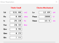
I wrote the above before loading it in HR only to find it's even worse than I assumed :The box only loads the driver to its upper mass corner (Fhm) where T/S theory peters out, so using the ZXI12.4D's (current) worst case Qts = 2.04, 25.18 Hz Fs and ignoring probably significant VC heating that will raise it:
Fhm = 2*Fs/Qts = ~24.7 Hz! There's under-damped ('ringing') and then there's this razor thin source of irritating VLF noise that will probably cook the driver even at low power as heat rise pushes it ever further below Fs, hence my 'strongly' suggestion to all within the 'sound of my voice' to not consider it for anything audio related beyond driving anybody/animal 'off the rails', so we'll have to 'agree to disagree'.
Fs: Fhm*Qts'/2
Qts': 2*Fs/Fhm
https://web.archive.org/web/20220707003028/http://www.mh-audio.nl/Calculators/newqts.html
In HR's default IB its ~infinite acoustic loading pushes its impedance loading down to ~11 Hz and its FR is just a default prediction of its HF based on its inductance (Le), which likely is just as useless.
For instance; in 70 L, 2 kW gets us an Xmax limited peaking @ ~18 Hz with a flattening power response at a dismal 90 dB + a whopping 146 ms GD @ ~13 Hz!
Attachments
One more to add to the mix. Does this make for EDM/Dub capable microPA type candidate? There would be four in total. They are proportioned to form stands for the tops and the driver in the mouth/exit down low to keep CG low
Cant seem to do much more so will make some boxes and start listening
Red is Eq on
Cant seem to do much more so will make some boxes and start listening
Red is Eq on
Attachments
At a glance, I trust HR enough to say they're designs worth experimenting with if Qt isn't too high, but you've yet to measure some broken in driver specs, so 'color me done' for now.Touched up a bit more, and now I also figured out how to apply full power
I am no where close to understanding this. 0.534 seems ok, doesn't it?I was referring to the wide range of Qt specs that includes an up to a Qts too high to be of any use in a typical HIFI/HT app
GM
When I spoke to DS18 tech, they said that they are re measuring all the drivers at the moment to collect the broken in data. This could imply the listed specs are virgin drivers
Let's measure this thing. Will report back on this after sorting out the PC situation sometime today. Also, what would you suggest for a sealed box size to break this in the car?
No clue; my last prosound involvement was with the Atlanta Rhythm Section's (ARS) 1975 "Dog Days" album debut at Road Atlanta. Truly a Labor Day three day weekend of 'infamy' for me and thousands of others for various and sundry reasons. A truly 'you had to be there' event.Does this make for EDM/Dub capable microPA type candidate?
Which program is more reliable? Or is it the output graph resolution that makes the hump appear pronounced. The following are the same 20L sealed sub in WinISD and that box ported to Fb=Fs 31.4Hz. They look so much better in WinISD
Why does HR show a humped response for sealed and WinISD doesnt?
Last edited:
Yes and no, depending on how much 'we' want to adhere to following T/S theory: https://www.diyaudio.com/community/...uild-with-some-more-bass.355384/#post-6227208I am no where close to understanding this. 0.534 seems ok, doesn't it?
Also, what would you suggest for a sealed box size to break this in the car?
Dunno, this is an upscale/$$ sealed I did for a Honda Accord that once EQ'd to 'taste' did Mexican polka - symphonies equally well depending on EQ chosen:How is this for a sealed test box for breaking in the driver in the car? Is this conical response normal for sealed?
Attachments
GMI was referring to the wide range of Qt specs that includes an up to a Qts too high to be of any use in a typical HIFI/HT app, so we'll have 'agree to disagree' due to the 'physics of the situation' :
I wrote the above before loading it in HR only to find it's even worse than I assumed :
In HR's default IB its ~infinite acoustic loading pushes its impedance loading down to ~11 Hz and its FR is just a default prediction of its HF based on its inductance (Le), which likely is just as useless.
For instance; in 70 L, 2 kW gets us an Xmax limited peaking @ ~18 Hz with a flattening power response at a dismal 90 dB + a whopping 146 ms GD @ ~13 Hz!
I noticed that our driver data is very different. Which numbers did you use? They look nothing like the manual
vs
Overall, HR, but in the box loading passband I assume they are identical other than need to compare each chart's vertical Vs horizontal scaling..........Which program is more reliable? Or is it the output graph resolution that makes the hump appear pronounced. The following are the same 20L sealed sub in WinISD and that box ported to Fb=Fs 31.4Hz. They look so much better in WinISD
Why does HR show a humped response for sealed and WinISD doesnt?
View attachment 1332775
- Home
- Loudspeakers
- Subwoofers
- Flared BR ports with Hornresp?