Rick, we need your mouth speaking good ideas and opinions as you always do.
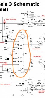
About the upside down transistor, this brought some passionate ideas interchange in that thread. Incredibly, the original Goldmund in that particular model has this transistor connected that way. I recall that some experts said at that time that this should work well no matter how weird it looks. When I assembled the PCB's I bought for this model, I inverted the transistor as I have seen it so many times in the Wilson mirrors. But here I uploaded the original schematic "as is"
This next week I will order the elements needed for the mods. The fixed amplifier will be tested a while and then returned to his owner. For the purpose of the modified schematic amp experiments, I suggest moving to a new thread just to be consistent with the title of this current thread. I will let you know when this happens.
Hello aparatusonitus and Rick !
I would like to open a new thread to build the new amplifier.
Do I count with you guys ?
I would like to open a new thread to build the new amplifier.
Do I count with you guys ?
I'm afraid I won't be too helpful ... my father will have surgery very soon (hopefully next Monday). If all goes well I will have to take care of his recovery from surgery, which will certainly not be easy given his age (82) and general health.
But I'll have my eye on your thread and chime-in when I have something to say.
But I'll have my eye on your thread and chime-in when I have something to say.
Dear aparatusonitus, blessings for your dad, everything will be OK, God will of course take good care of his health. Let us know the advances. I will open a new thread and will publish the link right here so you can check as it becomes possible to you.
I will honour the fact that these mods are yours. Please take care and my respects for your dad with my best wishes.
I will honour the fact that these mods are yours. Please take care and my respects for your dad with my best wishes.
I'm still available for additional fun 😉
Have to confess, though, my lack of expertise with LT Spice has (so far) confounded my study of the Exicon's stability and bias issues, and the possible magic of the flipped T5. Still pounding away, though.
We'll send a prayer or two for your dad's successful surgery and recovery, aparatusonitus.
Best Regards
I have a goldmund clone in this schematic. what changes should i make?I'm still available for additional fun 😉
Have to confess, though, my lack of expertise with LT Spice has (so far) confounded my study of the Exicon's stability and bias issues, and the possible magic of the flipped T5. Still pounding away, though.
We'll send a prayer or two for your dad's successful surgery and recovery, aparatusonitus.
Best Regards
R18 is way too small/low. All 4 output devices will be cutoff for a long time while the VAS transitions within ±2½V of Ground. It will also severely load the driver transistors, presumably misidentified as 'R59' and 'R85'. They'll be well over their dissipation rating by the time they stretch that 100 ohm resistor far enough to properly bias the outputs.
Way too many 33pF caps in the VAS. Looks like the designer had a lot of trouble getting it to stop bursting into oscillation.
Way too many 33pF caps in the VAS. Looks like the designer had a lot of trouble getting it to stop bursting into oscillation.
Last edited:
Agreed. Looks like just another broken design to me.R18 is way too small/low. All 4 output devices will be cutoff for a long time while the VAS transitions within ±2½V of Ground. It will also severely load the driver transistors, presumably misidentified as 'R59' and 'R85'. They'll be well over their dissipation rating by the time they stretch that 100 ohm resistor far enough to properly bias the outputs.
Way too many 33pF caps in the VAS. Looks like the designer had a lot of trouble getting it to stop bursting into oscillation.
C4 and C5 won't do anything without a resistor between them and the 'local bulks', C6 and C8.
Cheers
Cheers
First of all, thank you very much.. I will use 2x43v ac transformer 2x60vdcWhy do you want to change something? What voltage are the main rails?
Cheers
R18 vas resistor 100r 3w installed nowR18 is way too small/low. All 4 output devices will be cutoff for a long time while the VAS transitions within ±2½V of Ground. It will also severely load the driver transistors, presumably misidentified as 'R59' and 'R85'. They'll be well over their dissipation rating by the time they stretch that 100 ohm resistor far enough to properly bias the outputs.
Way too many 33pF caps in the VAS. Looks like the designer had a lot of trouble getting it to stop bursting into oscillation.
R18 çok küçük/düşük. VAS, ±2½V Toprak içinde geçiş yaparken, 4 çıkış cihazının tümü
VAS'ta çok fazla 33pF kapak var. Görünüşe göre tasarımcı , salınım patlamasını durdurmak için çok uğraşmış.
Instead of the 33pF caps on the VAS, I used the 22pf silver mica I had.Way too many 33pF caps in the VAS. Looks like the designer had a lot of trouble getting it to stop bursting into oscillation.

- Home
- Amplifiers
- Solid State
- Fixing and troubleshooting this MOSFET amplifier