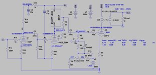
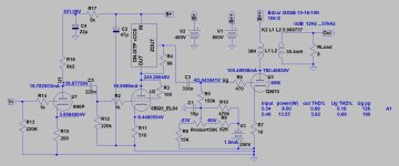
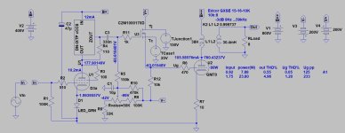
With the reported data, it's the @disso's amp simulation.
As you can see, with these parameters the CCS runs out from its headroom at larg/er/ swing.

As Erik wrote the V2= +300V is the one bottleneck, 400V would be better.

BTW, if I would use pentode, CCS and grid current hungry power tube, capacitor coupling isn't effective.
GM70 A1 limit is very low, over it grid sucks current like sand to water, in practice capacitor coupling blocking it.
So I would use high gm pentode as VAS, cathode or source follower to drive power tube.

These are ideas, OP have to consider what to do.
As you can see, with these parameters the CCS runs out from its headroom at larg/er/ swing.

As Erik wrote the V2= +300V is the one bottleneck, 400V would be better.

BTW, if I would use pentode, CCS and grid current hungry power tube, capacitor coupling isn't effective.
GM70 A1 limit is very low, over it grid sucks current like sand to water, in practice capacitor coupling blocking it.
So I would use high gm pentode as VAS, cathode or source follower to drive power tube.

These are ideas, OP have to consider what to do.
Thank you for your continued efforts to help me improve my amp 🙂
Your A2 proposal looks quite good, maybe i will implement it at some point. I have some 6E5P's which should work too but they probably need more than 2V input.
I measured all the voltages now and some are quite far off from the simulation while others are remarkably close:
Driver Stage B+: 320V
6N6P Anode: 225V
6N6P Cathode: 9.6V
6N6P Output with 2Vpp in:

EL84 Anode: 243V
EL84 Cathode: 8.9V
EL84/CCS Output with 2Vpp in:

So yea that stage runs out of headroom - 243V + 90V = 333V more than the supply provides. Looks like i need to decrease the cathode resistor. By the way, it's not an EL84 but a 6P14P-EV (was under the impression they are equivalent tho).
Output Stage B+ with both Tubes at 100mA: 850V. I don't know why all the sims show around 780, i suppose the transformer actually puts out more than specced.
GM70 Cathode at 100mA: -61V
Oh and my output transformer has a 7K primary (Toroidy TTG-GM70SE)
Your A2 proposal looks quite good, maybe i will implement it at some point. I have some 6E5P's which should work too but they probably need more than 2V input.
I measured all the voltages now and some are quite far off from the simulation while others are remarkably close:
Driver Stage B+: 320V
6N6P Anode: 225V
6N6P Cathode: 9.6V
6N6P Output with 2Vpp in:
EL84 Anode: 243V
EL84 Cathode: 8.9V
EL84/CCS Output with 2Vpp in:
So yea that stage runs out of headroom - 243V + 90V = 333V more than the supply provides. Looks like i need to decrease the cathode resistor. By the way, it's not an EL84 but a 6P14P-EV (was under the impression they are equivalent tho).
Output Stage B+ with both Tubes at 100mA: 850V. I don't know why all the sims show around 780, i suppose the transformer actually puts out more than specced.
GM70 Cathode at 100mA: -61V
Oh and my output transformer has a 7K primary (Toroidy TTG-GM70SE)
Yes it is and you are right!Another question. Is the 10R cathode resistor in the GM70 cathode a metal film type ?
Cathode current drops some 20mA under full load with a square wave (in fact it also drops a bit with a sine) but B+ does not.
Replacing this with a Wirewound type and improving the driver stage to not clip early will hopefully get me a bit more than the 11W out it does now 🙂
Last edited:
The problem is that it has way too much gain at that operating point, i don't need much more than 10Vpp on the 6P14 grid. Maybe not the best choice of input tube..It does not affect the fluctuation, but 6N6P operating point isn't optimal.
Near 200V, 10mA, -9V is on the right side of curves (on the curved section), so distortion can be measured even at low swing.
I would use it around 120-140V, 15-20mA, -4V.
only with tons of feedback:
i simulated lots of different driver stages when i first started designing this amp and this one yielded the best results. Rookie mistake tho, paying more attention to what Spice says than the tube's datasheets/loadlines 😴
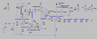
2nd Best was this:
Last edited:
You're right, it looks good. In my sim i can get 24W with 7Vpp in, my DAC can do 5.6Vpp max.
Tempting i must say. Just need to find a small-ish transformer to generate the +/-200V, not much space left in the amp.
Tempting i must say. Just need to find a small-ish transformer to generate the +/-200V, not much space left in the amp.
Today i put 2K2 in parallel with the 390R cathode resistor of the 6P14, this lowered anode voltage to 214V and it no longer hits the rail at full input.
This increased output power to about 13W.
I also replaced the cathode resistor of the GM70s with some wirewound ones (and made the distance from cathode to ground a lot shorter) but this made no difference, the cathode voltage still starts to sag at ~140vpp on the grids.
Apart from the sagging cathode voltage i'm satisfied with the amp for now, it sounds fantastic. In the long run i may change the driver stage to the A2 variant euro21 proposed.
If you crosses the A1 border, the capacitor prevent to put current to the output tube grid, so blocking occurs.... the cathode voltage still starts to sag at ~140vpp on the grids.
CF or SF solves this problem.
- Home
- Amplifiers
- Tubes / Valves
- Fixed Bias Oscillation on GM70 SE Amp
