It is a lot of trouble to use fixed adjustable bias, like so many pots, parts, and having to do adjustments back and forth so all tubes are at the same current, (and if you use a separate bias transformer and forget to turn it on first . . . watch out!).
Or, do like I most often did, use individual self bias resistors; only 2 parts per tube (resistor and bypass capacitor).
Simple, reliable, easy.
Plug and Play.
Or, do like I most often did, use individual self bias resistors; only 2 parts per tube (resistor and bypass capacitor).
Simple, reliable, easy.
Plug and Play.
Last edited:
Tuberabbit,
I should not have said ANY ripple.
So, where do we go from here . . .
Calculate the ripple voltage of a power supply.
Calculate how much hum that will cause at the output transformer secondary.
How much hum do you get?
How much is too much?
One answer for the very inefficient Radialstrahler loudspeakers 2 meters away.
Another answer for some very efficient Klipschorns that are across a 20 foot room.
A third answer for super efficient headphones on your ears.
Most of my amplifiers put out less than 100uV into 8 Ohms.
Is that good enough for you?
(not for most headphones, I use loudspeakers).
This circuit is used in Scott amplifiers. Power transformer has special bias winding for the purpose. Yes, bias voltage is not adjustable, unless the winding has taps. But adjustment is convenience, not necessity. The voltage can be chosen for a bogey tube, and some variation of idle current is acceptable. In a PP power stage, tubes have to be matched anyways, so can be biased from the same source.
It may take relatively short time to charge a capacitor to the peak voltage. If DC resistance of transformer winding and forward resistance of the diode are low, the capacitor may be fully charged in a fraction of a second. Can see it in PSUD2, just use a megohm load.
Discharging bias capacitor is not needed - there is no harm in bias voltage present after turn-off.
Grid becomes negative a volt or two in operation, which is used for grid leak bias. But negative bias voltage in a typical A1 or AB1 power stage is at least an order of magnitude higher, it will swamp negative charge of electrons trapped by grid. Positive grid current due to gas or internal plate-grid leakage is vanishingly small compared to capacitor charging current, and can be disregarded for a healthy tube. Of course, this scheme only works for A1 or AB1, it won't work for A2 or AB2.
Yes, 10,000 micromhos tubes will need individual bias adjustment because they are PITA to match. But with typical audio output tubes of 2,000-6,000 micromhos such adjustment may be unnecessary.

sser2,
OK, you are correct about some Scott amplifiers, but . . .
This thread is about how to bias KT-150 tubes . . .
KT-150 Transconductance, Gm = 12,600 micro Mhos !
Do Not use the Scott fixed bias circuit to bias KT150 tubes !
Note:
KT-150 maximum g1 grid return resistance is only 51k Ohms for fixed bias.
KT-150 maximum g1 grid return resistance is 240k Ohms for self bias.
Make the load on the driver tube easier, make biasing easier, make tube matching less of an issue, make the job of first power up easier;
That all happens when you use self bias on KT-150 tubes.
Just my opinions (perhaps a few others will agree with me).
Last edited:
i highly doubt this, there is leakage current around the capacitor to ground, power that up, then turn it off and after some time the capacitor discharges..this is real world...View attachment 1208331
Zero ripple.
sadly often overlooked, high gm tubes can easily bias runaway at the slightest provocation, so i will use cathode followers for this...Note:
KT-150 maximum g1 grid return resistance is only 51k Ohms for fixed bias.
KT-150 maximum g1 grid return resistance is 240k Ohms for self bias.
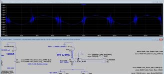
I checked in LTspice how ripple bias affects the voltage on the secondary winding of the output transformer. The result is about a few uV rippe.Calculate how much hum that will cause at the output transformer secondary.
However, the jagged graph in LTSpice is disturbing, especially around the zero crossing.
I don't know if it's some bug in the LTSpice simulation or if I set something wrong or if there is some kind of resonance going on...
Attachments
Or, do like I most often did, use individual self bias resistors; only 2 parts per tube (resistor and bypass capacitor).
Simple, reliable, easy.
Plug and Play.
Make the load on the driver tube easier, make biasing easier, make tube matching less of an issue, make the job of first power up easier;
That all happens when you use self bias on KT-150 tubes.
Just my opinions (perhaps a few others will agree with me).
@6A3sUMMER You are right, self-bias is a simple and reliable solution (although it is worth taking care of a good quality bypass cap).
Fixed-bias also has its advantages, especially with larger power tubes. I would like to try fixed-bias in my project...
My Balanced amplifier uses a single self bias cathode resistor for the ECC82 input/driver tube.
The ECC82 cathodes are directly connected; as one cathode draws more current, the other cathode draws less current.
There is No bypass cap across the single self bias resistor (not needed).
That Balanced amplifier also uses a single self bias cathode resistor for the 5881 Triode wired output tubes.
The 5881 cathodes are directly connected; as one cathode draws more current, the other cathode draws less current.
There is No bypass cap across the single self bias resistor (not needed).
The only thing that makes that work properly is the extremely well matched triodes of the ECC82; and the extremely well matched 5881 output tubes.
I get my excellent JJ ECC82 and JJ 5881 tubes from Eurotubes.com (I am able to drive there and pick the tubes up).
Eurotubes ships to many overseas countries.
That amplifier is quite simple, is low powered (I choose that), and requires a Balanced signal source (I have a Marantz CD player with XLR L and R channel outputs).
Many early push pull amplifiers used well matched output tubes, a single self bias resistor, and did not use a bypass cap across the resistor.
I did not like that idea, but I tried it . . .
Well, now I like that idea.
The balanced amplifier is a big departure from the many tube amplifiers I designed and built before.
Balanced Sounds Great!
The issue is how much ripple will be caused by capacitor leakage current (microamperes for electrolytes, nanoamperes for film capacitors) Some capacitors (for example teflon) have such small leakage that they will retain charge for weeks. This was used in radiation monitors.i highly doubt this, there is leakage current around the capacitor to ground, power that up, then turn it off and after some time the capacitor discharges..this is real world...
PSUD2 gives good ripple voltage estimate for a given leakage current. For 10M leakage resistance, it is practically zero.
I am so glad that all tube grids, g1, only draw Femto Amps of quiescent grid current.
Oh, Sorry, that is Not true.
All tubes are equal, some tubes are more equal than others.
A lot of tubes are biased at or near to the Contact Potential.
That is not the tube's fault, it is the circuit designer's fault.
We are talking about Hi Fi stereo amplifiers, not Laboratory Electrometers.
Just my opinions
no point to debate this, you can have your way...The issue is how much ripple will be caused by capacitor leakage current (microamperes for electrolytes, nanoamperes for film capacitors) Some capacitors (for example teflon) have such small leakage that they will retain charge for weeks. This was used in radiation monitors.
PSUD2 gives good ripple voltage estimate for a given leakage current. For 10M leakage resistance, it is practically zero.
i used to do pp amps like that with common cathode resistor bias, nowadays it is one cathode resistor per tube, the higher resistance resulting from separates makes for better protection for the the output tube and the output transformers too..Many early push pull amplifiers used well matched output tubes, a single self bias resistor, and did not use a bypass cap across the resistor.
I did not like that idea, but I tried it . . .
Well, now I like that idea.
as far as the sound goes, i hear no difference at all...
The GEC application notes for the KT66 asserts: it is essential to use two separate bias resistors. This PP AB1 triode connected.
The more voltage, current, and dissipation you operate a tube at; Versus its maximum specifications,
The more care in biasing, g1 return resistor, keeping the B+ from shooting up when the power mains shoots up, etc., you have to pay attention to all the details.
Such as whether you use fixed bias, individual fixed bias, self bias, or Individual self bias . . . becomes more important of a decision.
Individual self bias is the most reliable of those, common fixed bias is the least reliable.
Hints:
In Beam Power mode, as long as you regulate the screen voltage (like a series pair of OD3 gas tubes, 300V), then when the power mains voltage varies, and B+ increases, the Plate current hardly varies. That is because the plate impedance, rp, is very high.
In Triode Wired mode, the screen voltage is the same as the plate voltage. And the plate impedance, rp, is very low (compared to Beam Power mode). If the B+ increases, Both the plate voltage, And the screen voltage increase.
So, when the power mains voltage varies, and the B+ voltage increases, the plate current increases.
You thought you were within the maximum ratings of the tube, but then the B+ voltage increased.
Something to think about.
Last edited:
- Home
- Amplifiers
- Tubes / Valves
- Fixed bias design