Hello 🙂
I am designing a fixed bias circuit.
Although the bias circuit is not complicated, several doubts arose during the design process...
I have no experience in building amplifiers, so any advices, tips, suggestions or approve will be appreciated 🙂
Maybe I forgot something or made a design mistake?
Design
The bias circuit is designed for a parallel single ended power stage with two KT-150 valves per channel.
-bias will be powered by a separate transformer (it will be custom made to order)
-each channel will have its own transformer/PSU circuit (dual-mono design)
Safety resistor
Many schematics found on the net lack a safety resistor protecting the valve from burning if the pot's wiper goes open.
In the circuit shown, there is a safety resistor 200 kOhm.
KT-150 datasheet resistance
KT-150 maximum grid circuit resistance for fixed bias is only 51 kOhm.
I assume that the value of 51 kOhm "Maximum grid 1 Circuit Resistance / fixed bias" given in the datasheet is the grid to cathode/ground resistance.
(There may also be the grid to bias power supply resistance (cap)...or... grid to cathode/ground resistance through the psu ground???)
There will be two valves per channel (paraller single ended), so the driver will be loaded with a parallel combination of its own anode load (choke) and two resistances in the power stage.
(A grid choke could increase the impedance, but so far the design does not include it)
In the diagram shown, the grid-to-cathode (ground) resistance is approximately 51-53kOhm, depending on the bias setting.
Adjustment range
The bias adjustment range is useful for experimentation: -40 to -60 volts
(Need about -50V for quiescent point 129mA/480V anode voltage, dissipation <90%)
Resistance change
I tried to ensure that the change in the bias voltage did not cause a large change in the resistance value of the bias circuit.
In the diagram shown, a change in the bias voltage in the range of -40 to -60 volts causes a small change in the grid-to-cathode/ground resistance: 51-53kOhm.
Voltage filtering
The bias voltage should be properly filtered, because a small change in the bias voltage causes a large change in the current flowing through the valve.
The PSUD simulation shows fluctuations around 70uV peak to peak (when the transformer has 100ohm resistance and the reservoir cap is 100uF)
Is this filtering value enough? 🙂
Transformer
I am wondering what VA power of the transformer to choose and what its resistance will be.
Probably the power should be several VA and the resistance will be several hundred ohms (smaller VA -> greater resistance).
The VA formula is: Vpri x Ipri or Vsec x Isec. Plus, a little oversize...
Resistance formula: Rs(equiv) = Rsec + Rpri/(Vpri/Vsec)^2
The required transformer voltage is related to the resistance (...and the reservoir cap), I don't know the formula to calculate this dependence.
The PSUD simulation shows the following RMS AC no-load voltages (rounded values), depending on the transformer resistance:
1Ω - 74V (theoretical resistance value, for powerful transformers)
50Ω - 77V
100Ω - 80V
200Ω - 85V
300Ω - 89V
400Ω - 93V
500Ω - 97V
600Ω - 100V
700Ω - 104V
800Ω - 107V
900Ω - 110V
1000Ω - 113V
2000Ω - 141V
The bias circuit draws a small amount of current, about 20.5 mA (although for the bias circuit, this can be quite a lot).
When the power supply has 100ohms of resistance (probably the value will be higher...) and the 100uF reservoir capacitor (crucial for good voltage filtering but resulting in higher current "spikes"), the PSUD shows:
-peaks of current drawn from the transformer -115mA / + 115mA, during normal operation
-During startup, the inrush current fluctuates between +860mA / -560mA.
So, 3VA / 4VA should be enough? 🙂


Resistance to psu cap
The signal may be going back to bias power supply cap, isn't that a rather desirable behavior?
A large 47kOhm resistor should provide high signal resistance to the bias power supply.
Potentiometer
The pot is Bourns 3549S-1AC-202B, withstands 2W.
Special resistors
Will the use of non-magnetic or non-inductive resistors bring any benefits?
SiC Schottky Diodes
Would using SiC Schottky Diodes (Woolfspeed CSD01060E or CSD01060A) instead of 1N4007 be a good idea?
I am designing a fixed bias circuit.
Although the bias circuit is not complicated, several doubts arose during the design process...
I have no experience in building amplifiers, so any advices, tips, suggestions or approve will be appreciated 🙂
Maybe I forgot something or made a design mistake?
Design
The bias circuit is designed for a parallel single ended power stage with two KT-150 valves per channel.
-bias will be powered by a separate transformer (it will be custom made to order)
-each channel will have its own transformer/PSU circuit (dual-mono design)
Safety resistor
Many schematics found on the net lack a safety resistor protecting the valve from burning if the pot's wiper goes open.
In the circuit shown, there is a safety resistor 200 kOhm.
KT-150 datasheet resistance
KT-150 maximum grid circuit resistance for fixed bias is only 51 kOhm.
I assume that the value of 51 kOhm "Maximum grid 1 Circuit Resistance / fixed bias" given in the datasheet is the grid to cathode/ground resistance.
(There may also be the grid to bias power supply resistance (cap)...or... grid to cathode/ground resistance through the psu ground???)
There will be two valves per channel (paraller single ended), so the driver will be loaded with a parallel combination of its own anode load (choke) and two resistances in the power stage.
(A grid choke could increase the impedance, but so far the design does not include it)
In the diagram shown, the grid-to-cathode (ground) resistance is approximately 51-53kOhm, depending on the bias setting.
Adjustment range
The bias adjustment range is useful for experimentation: -40 to -60 volts
(Need about -50V for quiescent point 129mA/480V anode voltage, dissipation <90%)
Resistance change
I tried to ensure that the change in the bias voltage did not cause a large change in the resistance value of the bias circuit.
In the diagram shown, a change in the bias voltage in the range of -40 to -60 volts causes a small change in the grid-to-cathode/ground resistance: 51-53kOhm.
Voltage filtering
The bias voltage should be properly filtered, because a small change in the bias voltage causes a large change in the current flowing through the valve.
The PSUD simulation shows fluctuations around 70uV peak to peak (when the transformer has 100ohm resistance and the reservoir cap is 100uF)
Is this filtering value enough? 🙂
Transformer
I am wondering what VA power of the transformer to choose and what its resistance will be.
Probably the power should be several VA and the resistance will be several hundred ohms (smaller VA -> greater resistance).
The VA formula is: Vpri x Ipri or Vsec x Isec. Plus, a little oversize...
Resistance formula: Rs(equiv) = Rsec + Rpri/(Vpri/Vsec)^2
The required transformer voltage is related to the resistance (...and the reservoir cap), I don't know the formula to calculate this dependence.
The PSUD simulation shows the following RMS AC no-load voltages (rounded values), depending on the transformer resistance:
1Ω - 74V (theoretical resistance value, for powerful transformers)
50Ω - 77V
100Ω - 80V
200Ω - 85V
300Ω - 89V
400Ω - 93V
500Ω - 97V
600Ω - 100V
700Ω - 104V
800Ω - 107V
900Ω - 110V
1000Ω - 113V
2000Ω - 141V
The bias circuit draws a small amount of current, about 20.5 mA (although for the bias circuit, this can be quite a lot).
When the power supply has 100ohms of resistance (probably the value will be higher...) and the 100uF reservoir capacitor (crucial for good voltage filtering but resulting in higher current "spikes"), the PSUD shows:
-peaks of current drawn from the transformer -115mA / + 115mA, during normal operation
-During startup, the inrush current fluctuates between +860mA / -560mA.
So, 3VA / 4VA should be enough? 🙂
Resistance to psu cap
The signal may be going back to bias power supply cap, isn't that a rather desirable behavior?
A large 47kOhm resistor should provide high signal resistance to the bias power supply.
Potentiometer
The pot is Bourns 3549S-1AC-202B, withstands 2W.
Special resistors
Will the use of non-magnetic or non-inductive resistors bring any benefits?
SiC Schottky Diodes
Would using SiC Schottky Diodes (Woolfspeed CSD01060E or CSD01060A) instead of 1N4007 be a good idea?
Hi, for fixed bias supply's I use a bridge rectified supply like yours but 1k & 220u RC filters will take too long to charge the cap, you want that bias supply there before the valves warm up, better to use something like 100r to 220r.
Second a 2k pot won't give you much adjustment I think. I usually use a 20k or 10k pot. A good rule of thumb is 2k per volt, this is from experience. this does increase the grid leak value though. Also I use two 1M resistors from each leg of the pot to the wiper, and de-couple the wiper to ground with something like a 10u cap.
It won't hurt if you have the room to make the tfmr bigger, it has to have enough current to charge those 220u caps, I wind my own tfmrs and make the bias winding capable of 100mA, a bit excessive perhaps but it doesn't hurt. I want a bias supply that is rock solid.
Lastly you have no fuse protecting the tfmr etc. If you have the room and are getting the tfmr custom made fit a protection circuit so that if ecah OP valve pulls too much current the amp switches off. See attached. This is what Pat Turner designed for one of his amps, I've used this circuit in a few of my big amps suitably altered for the OP stage.
Andy.
Attachments

Using a separate bias transformer creates i dangerous situation IF the bias circuit by any reason does not work.
By using the output from the bias circuit to energize a relay that closes the main transformers connection to mains could
prevent this. It also makes life easier for the circuit breaker since it only needs to power a small transformer.
By using the output from the bias circuit to energize a relay that closes the main transformers connection to mains could
prevent this. It also makes life easier for the circuit breaker since it only needs to power a small transformer.
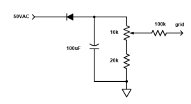
Too complicated. Since negatively biased grid draws no current, an adequate bias supply is a single diode charging a single capacitor. The capacitor is charged to peak voltage and maintains it. There is no ripple. This circuit was used in many commercial fixed bias amplifiers, for example Scott. If you want adjustable bias voltage, use transformer with secondary taps.
If one tube's limiting grid resistance value is 50K, for two parallel tubes it is 25K. You should seriously consider a grid choke.
If one tube's limiting grid resistance value is 50K, for two parallel tubes it is 25K. You should seriously consider a grid choke.
A complete and accurate schematic of your Parallel Single Ended KT-150 amplifier is worth 1,000 Words, and will save you about 100 Posts in this thread.
l prefer Individual self bias for output tubes (my preference, not yours).
If the tubes are even somewhat well matched, the currents will be very close to equal.
Easy, "Plug and Play".
You prefer fixed bias, so . . .
I hope you are planning to use Individual adjustable fixed bias for each tube.
Just remember, each time you adjust the bias on one tube, the current in the other tube may vary (unless you have a well regulated B+ voltage).
Without Individual self bias pots, you need Extremely Well Matched KT-150 tubes.
Every design decision has a tradeoff of some sort.
Have fun designing, building, adjusting . . . and Listening!
Last edited:
Too complicated. Since negatively biased grid draws no current, an adequate bias supply is a single diode charging a single capacitor. The capacitor is charged to peak voltage and maintains it. There is no ripple. This circuit was used in many commercial fixed bias amplifiers, for example Scott. If you want adjustable bias voltage, use transformer with secondary taps.
If one tube's limiting grid resistance value is 50K, for two parallel tubes it is 25K. You should seriously consider a grid choke.
The FWB rectifier circuit is fine, and will not have 60 Hz ripple like a half wave rectifier.
A half wave rectifier from a HV secondary tap is used in many circuits mainly for its low cost.
The resistive bias divider definitely does discharge the input capacitor, so there is 60 Hz voltage ripple.
There is indeed one 47k grid resistor per output tube, not per pair, in the circuit given.
ANY ripple on a fixed bias supply will cause Lots of Hum on a Single Ended Amplifier
The same amount of ripple on a fixed bias supply will cause Far Less Hum on a Push Pull amplifier.
Guess what this thread is about?
. . . A Single Ended amplifier.
Designer beware!
The same amount of ripple on a fixed bias supply will cause Far Less Hum on a Push Pull amplifier.
Guess what this thread is about?
. . . A Single Ended amplifier.
Designer beware!
Half-wave bias rectifier + capacitor will not have any ripple at all. No current, no ripple. Capacitor charges to the peak voltage and maintains it, since there is no discharge current.
make that individual bias pots, one for each grid....and separate cathode resistors for monitoring cathode currents.. you may have to go over each settings or pot adjustments many times over since one setting affects the other, good luck with that..
Half-wave bias rectifier + capacitor will not have any ripple at all. No current, no ripple. Capacitor charges to the peak voltage and maintains it, since there is no discharge current.
So in this example bias circuit, you say there is NO ripple, and no discharge current from the capacitor?
At 60 Hz line frequency, and for t = 0 to 16.7mS (one cycle), at max voltage setting of the bias pot, we have:
Vout = 50 * sqrt (2) * e^( - t / ( 30k * 100uF ) )
That looks like voltage ripple to me, but it's been a long time since EE 101.
If you want to know how much ripple, plug in t = 16.7mS and see how much the bias voltage sags from (50 * sqrt 2 ) volts.
I get about 0.39 V sag in one cycle. That seems like ripple to me, in fact too much ripple.
Attachments
Last edited:
Compare these two waveforms from:
https://instrumentationtools.com/ripple-voltage-rectifiers/
https://instrumentationtools.com/ripple-voltage-rectifiers/
Attachments
ideal case will have no load currents, but real life bias circuit have current loads, if only to drop voltage across voltage divider resistors...
Once you have a resistor to ground, it's no longer ideal. The resistors in the above example draw 2.3mA per tube.
Thanks for the many replies 🙂
Each valve will have its own pot and a small cathode resistor (1 ohm, not visible in the diagram) to measure the bias (I know a small screen current will also flow through the cathode...)
Thus, the bias and heaters will be switched on first, and the anode voltage next.
This won't be a convenient way to turn on the amp, but for my experiments, it'll be fine 🙂
Each of the valves will have its own 47kOhm grid leakage resistor but...
I mentioned that in the description: "Driver will be loaded with a parallel combination of its own anode load (choke) and two resistances in the power stage."
Heavy loaded driver means less horizontal loadline and higher THD from the driver stage (admittedly, even distortions will cancel out between stages, unlike odd ones).
I would need four grid chokes, I think I will try in a future upgrade...
When designing the circuit, I was inspired by this site: https://www.valvewizard.co.uk/bias.html
make that individual bias pots, one for each grid....and separate cathode resistors for monitoring cathode currents..
That's the plan (in my diagram it is represented as: "The same as above, for the second valve KT150").I hope you are planning to use Individual adjustable fixed bias for each tube.
Each valve will have its own pot and a small cathode resistor (1 ohm, not visible in the diagram) to measure the bias (I know a small screen current will also flow through the cathode...)
I didn't draw it on the diagram, but the idea is that the bias circuit has its own separate power switch (similar to the valves heaters power supply).1k & 220u RC filters will take too long to charge the cap, you want that bias supply there before the valves warm up, better to use something like 100r to 220r.
Thus, the bias and heaters will be switched on first, and the anode voltage next.
This won't be a convenient way to turn on the amp, but for my experiments, it'll be fine 🙂
If one tube's limiting grid resistance value is 50K, for two parallel tubes it is 25K. You should seriously consider a grid choke.
There is indeed one 47k grid resistor per output tube, not per pair, in the circuit given.
Each of the valves will have its own 47kOhm grid leakage resistor but...
I mentioned that in the description: "Driver will be loaded with a parallel combination of its own anode load (choke) and two resistances in the power stage."
Heavy loaded driver means less horizontal loadline and higher THD from the driver stage (admittedly, even distortions will cancel out between stages, unlike odd ones).
I would need four grid chokes, I think I will try in a future upgrade...
It's true :/ I think that the future, more mature version of the amplifier will have some protection.Using a separate bias transformer creates i dangerous situation IF the bias circuit by any reason does not work.
I forgot to draw on the diagram, I plan to put the fuse in the circuit.Lastly you have no fuse protecting the tfmr etc.
It looks amazing and ...complicated, I have too little experience to build such systems 🙂This is what Pat Turner designed for one of his amps
When designing the circuit, I was inspired by this site: https://www.valvewizard.co.uk/bias.html
The only way I know to get rid of ripple, is to use batteries :/ANY ripple on a fixed bias supply will cause Lots of Hum on a Single Ended Amplifier
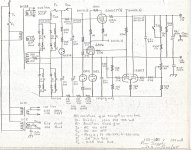
I haven't used a separate transformer or a tap off the HV winding since just after the Earth cooled & there were Silicon rectifiers at reasonable cost.
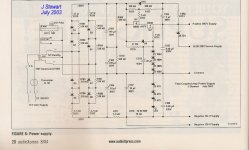
The negative rail can easily be got to fill the requirements of most amplifiers from the same HV wdg as the B+.
The negative rail in the year 1965 Reg PS example provides the negative reference voltage & operating voltage for the AX7 error amplifier.
In the more recent supply the negative voltage supplies the tails of a 2-stage diff amp & negative bias to the amps PP 6LU8 output stage.
Attachments
The interesting and simple solution.
Zero ripple.
Is this used in any tube amp? I have a few doubts:
- Zero ripple is impossible to achieve. This is because it takes forever to fully charge a capacitor with pulsating current. However, the more time passes, the smaller the ripple will be. The LTSpice simulation shows 0.000008V PP after 8 minutes (cap: 100uF). My circuit provides 0.00006V PP.
- There is no way to change the bias voltage.
- Something to discharge the cap after the amplifier is turned off would be needed.
- Grid current can be positive or negative (reverse). Sometimes the electrons flow into the grid, sometimes out of the grid. In the picture above (zero-ripple) electrons can only flow in one direction? Grid current is described in this post: https://www.diyaudio.com/community/...eed-grid-leak-resistance.261130/#post-4570389
sser2,
Congratulations, your scheme works.
But not very well . . .
Are you going to add or take turns off of the secondary to get the proper bias voltage you want.
That would be your special version of "fixed Adjustable bias".
Be sure to have individual transformers for each output tube (if you do not use extremely well matched output tubes).
A modern output tube with a transconductance of 10,000 microMhos will change plate current by 5mA if a single extra secondary turn adds 0.35Vrms, which would add 0.5VDC to the bias voltage.
(That is 0.5VDC bias per single secondary turn, most secondaries do not have that much voltage resolution)
Are you willing to go to that much trouble?
Last edited:
- Home
- Amplifiers
- Tubes / Valves
- Fixed bias design