Heater current bias has some other advantages, and no cathode bypass...
- only one transformer secondary and DC supply for heat and bias together;
- stabilised DC heater is useful for high-gm drivers: stable gm at low frequency, and lower noise with high-gm driver, especially Soviet 6E5P, 6E6P
The opamp would probably work well, although it would require a whole lot of additional circuitry.. I might give it a try though..A general LDO can't handle a +2V output while sinking current. They're designed to provide source current.
So if you want to use an external source providing voltage directly to cathode, this is what you need.
View attachment 1252378
An OPAMP with Class AB output stage can provide +2Volts with -20mA output current. Some Series Voltage References can also provide sinking current capabilities.
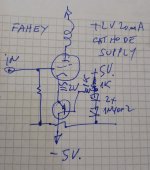
And by the way, a fixed -2V bias could result in different cathode current across tubes, so the adjustment section is necessary, especially for high Gm tubes. Unless you've tested your tubes previously. The 1 ohms resistor is placed to examine the current.
A 10 ohms resistor provides a large bias current can work. But I think an OPAMP can provide symmetrical response to both positive and negative transients, or CCS with a low value resistor which provide constant impedance across frequency, will be better than a biased low noise LDO.
* Yes you can apply +2V to cathode to bias it.
* Yes you can sink any current you need, with the proper design of course.
* You do not need to waste current (even less 200mA) to get puny 20mA out of a shunt circuit.
* You can do it using a series one.
* You can regulate it as much as you wish, add voltage references, Op Amps, a microprocessor, whatever; I am showing a basic "proof of concept" design to show it can be done.
* No 10 ohm resistor is needed. In fact you would be adding impedance where there was zero. Actually cathode capacitor reactance which we are trying to avoid.
* Your will get roughly +2V on cathode, actually "3 diode drops" above ground.
Should be close enough.
Feel free to add as much regulation and sophistication as you deem necessary.
Attachments

@Rod Coleman I am thinking about the following circuit.. I am leaving Ck and add a switch in series to it, so I can perform some blind testing with/without ck

Few years ago I tried this.

Worked ... but not cup of tee for me.
Series IR and Red LED was better (the IT primary was CCS feeded).
For DH tubes I usually use filament biasing, but for IDHT IMHO it's unnecessarily complicated, the tone not quite different as R//C.
Worked ... but not cup of tee for me.
Series IR and Red LED was better (the IT primary was CCS feeded).
For DH tubes I usually use filament biasing, but for IDHT IMHO it's unnecessarily complicated, the tone not quite different as R//C.
I ran some simulations, and it looks like the filament bias introduces higher local feedback (due to the ac component of Ik flowing through Rk), plus some Ik_ac would flow in the filament too. (I used Iac=1KHz in the simulation)


A better result is obtained by parallelizing the filament with the Rk, but that would require a lot of DC current to minimize the Vk swing..


From a frequency domain perspective: at the lower frequencies, it looks like the filament bias would be a better performer than the cathode bias, while at higher frequencies, the bypass capacitor would be more effective at shunting the ac component from Vk. The "parallel" bias looks like the best compromise, but a high current cost. I might try this last option since I don't mind to splurge on transformers and electricity bills.

A better result is obtained by parallelizing the filament with the Rk, but that would require a lot of DC current to minimize the Vk swing..
From a frequency domain perspective: at the lower frequencies, it looks like the filament bias would be a better performer than the cathode bias, while at higher frequencies, the bypass capacitor would be more effective at shunting the ac component from Vk. The "parallel" bias looks like the best compromise, but a high current cost. I might try this last option since I don't mind to splurge on transformers and electricity bills.
Also the 220 uF of the interstage and cathode"OP does not want capacitors"
OK.
Then must to remove "half of 47+47uF 500V Elna Cerafine" and all of PSU smoothing capacitors too, because all of them in the one of signal path. 😳
Walter
@JMFahey
According to the simulations, the BJT shunt driven by an an op-amp error amplifier on the paper seems to be much more efficient at removing the ac component from the cathode voltage across all the spectrum, compared to the bypass capacitor (unless I use an insanely large Cbypass )


According to the simulations, the BJT shunt driven by an an op-amp error amplifier on the paper seems to be much more efficient at removing the ac component from the cathode voltage across all the spectrum, compared to the bypass capacitor (unless I use an insanely large Cbypass )
Ck would need to be large to bypass 6.7R.@Rod Coleman I am thinking about the following circuit.. I am leaving Ck and add a switch in series to it, so I can perform some blind testing with/without ck
View attachment 1252797
For blind testing, the levels need to be equalised, as Rk gives a little helpful degeneration. The better linearity can usually be measured.
BJT shunt driven by an an op-amp error amplifier
If you give it a blind comparison, let us know!
47R of RB for the PNP is usually needed, or it may take off at VHF; and loop compensation for many op amps. If the audio signal phase is rotated as a consequence, it can be unhelpful, especially with linear phase crossover speakers.
I told you 😉@JMFahey
According to the simulations, the BJT shunt driven by an an op-amp error amplifier on the paper seems to be much more efficient at removing the ac component from the cathode voltage across all the spectrum, compared to the bypass capacitor (unless I use an insanely large Cbypass )
And to be more precise, it isn't shunting anything, it's straight feeding the cathode with nothing else involved.
"Series" feeding it if you wish, only from a very low impedance.
Efficient too, since all its current goes into the cathode.
Last edited:
You could use a single lead acid cell (2.1V on the grid instead of the cathode...
Here's an example using 3V from Broskie.

Here's an example using 3V from Broskie.
It is a cap in series to signal !You could use a single lead acid cell (2.1V on the grid instead of the cathode...
Here's an example using 3V from Broskie.
Orror! 🤣
It is a similar circuit used by Allnic ( if I remember well)
Walter
It will work, and given the no-current status of grids, you may even use an UFO/flying saucer shaped bias battery 😱You could use a single lead acid cell (2.1V on the grid instead of the cathode...
Here's an example using 3V from Broskie.
View attachment 1253825
it acts also as a capacitorIt will work, and given the no-current status of grids, you may even use an UFO/flying saucer shaped bias battery 😱
Walter
- Home
- Amplifiers
- Tubes / Valves
- Fixed bias applied to the cathode