No. They're designed to go on a flanged heatsink (a la the Sony VFET amplifiers, or Conrad's flanged heatsinks, etc.).
Hi Ernst,
They're made for a FirstWatt-style case. 14" long (13.96" actually), with 2" hole spacing.
Cheers,
Jeff.
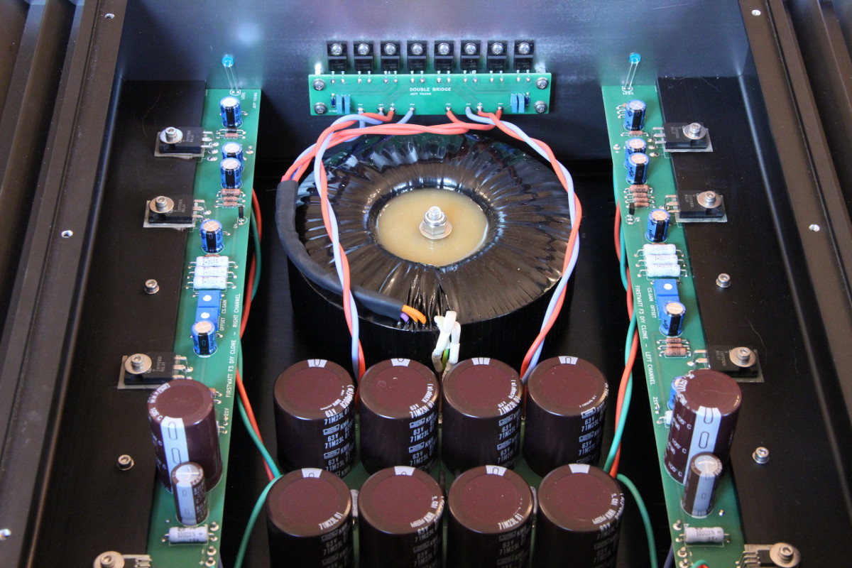
PS: here's a picture of my F3. J2 boards are same length and hole spacing, but a bit narrower.
@ JeffYoung
What is etc.?
@ JeffYoung
What is etc.?
I'm not going to hold your hand, Soundhappy. Go look in the group buy thread.
So do these PCBs work with the established UMS?
https://cdn.shopify.com/s/files/1/1006/5046/files/universal-mounting-specification-v2.1.pdf
No. They're designed to go on a flanged heatsink (a la the Sony VFET amplifiers, or Conrad's flanged heatsinks, etc.).
A Conrad style integral flange heat sink looks like a smart move to me. Given Jeff's long skinny board (350 mm / 14" 'ish), that could bolt to two 200 mm long heat sinks. My loose plan would be to bolt that together with the ModuShop rails, perforated bottom deck and end/cover plates.
Staying 😎 is where it's at for me. Warm climate. Plan for the worst and fans blow/suck (depending on which side you're standing).
Originally Posted by Soundhappy View Post
@ JeffYoung
What is etc.?
first, you highlight the word etc. using your mouse and click, search in google...
etc.
/etˈsedərə/
adverb
1.
used at the end of a list to indicate that further, similar items are included:
"protect seedling from damage caused by feet, lawnmowers, pets, etc."
Powered by Oxford Dictionaries
Funny, I like having the active devices bolted directly to the thick heat sink base.
Seems that it would conduct better. Either way works of course.
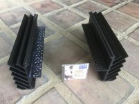
I’ll be using a flanged sink for a metal canned VFET amp though. The metal cans DO look cool lined up in the Sony, and I had these monster sinks with TO-3 holes. They've been sitting around for years, donated by np at the first Burning Amp. I was cleaning up after the show and found them on the floor halfway to the exit door Obviously someone realized that they couldn’t carry them all the way to their car! A couple of times I planned to mill off the flanges but luckily I didn’t. They’ll be the centerpiece of my system!
Seems that it would conduct better. Either way works of course.
I’ll be using a flanged sink for a metal canned VFET amp though. The metal cans DO look cool lined up in the Sony, and I had these monster sinks with TO-3 holes. They've been sitting around for years, donated by np at the first Burning Amp. I was cleaning up after the show and found them on the floor halfway to the exit door Obviously someone realized that they couldn’t carry them all the way to their car! A couple of times I planned to mill off the flanges but luckily I didn’t. They’ll be the centerpiece of my system!
Attachments
Last edited:

huh! I just realised I've a couple of old tokin and sony vfets kicking about without a purpose... It might well be fun to drop one of those in instead of the Semisouth...
The 2SK170s in the current source. They're each going to dump their Idss no matter what the other is doing, right? ...
In the schematics I posted, they do not dump their Idss.
The CCS current is made adjustable to trim DC offset.
You should think about how you set the bias current of the SRPP MOSFET.
And then how you adjust the bias of the SJEP to give zero DC.
No need to follow mine. You can also look at what ZM posted in his zip file.
Patrick
huh! I just realised I've a couple of old tokin and sony vfets kicking about without a purpose... It might well be fun to drop one of those in instead of the Semisouth...
depletion parts
calling for solution with additional (more) negative rail and small CCS , which Patrick gave several years ago ( for Aleph J craddle) , when I was even dumber than today
🙂
...I had these monster sinks...
Nice, if you put those on Swap Meet, you'll lose your arm 😀
In the schematics I posted, they do not dump their Idss.
The CCS current is made adjustable to trim DC offset.
You should think about how you set the bias current of the SRPP MOSFET.
And then how you adjust the bias of the SJEP to give zero DC.
No need to follow mine. You can also look at what ZM posted in his zip file.
Patrick
Thanks, Patrick!
(I use a normal resistor and just change the value in SPICE, but the drain resistor will be a potentiometer "in the flesh".)
Carefully read; mostly understood; no flash of insight.
I thought the concern might be "what happens if the pot is set to 0", under which conditions we get a the rail - the CCS Vgs on to the output. But that just turns the opto-coupler off.
Another hint?
I thought the concern might be "what happens if the pot is set to 0", under which conditions we get a the rail - the CCS Vgs on to the output. But that just turns the opto-coupler off.
Another hint?
Tolerances on current transfer ratio and forward voltage.
You can change those in your spice file and see what happens to the bias.
Patrick
You can change those in your spice file and see what happens to the bias.
Patrick
Tolerances on current transfer ratio and...
Seems like it would be better to ditch the LED and connect the BJT base to the 100R, ie. revert to a conventional two transistor CCS (obviously all resistor values will change).
The LED has the advantage of a lower temperature coefficient than the
junction of an npn transistor.
junction of an npn transistor.
The LED has the advantage of a lower temperature coefficient than the
junction of an npn transistor.
Interesting, I take it you mean the opto (as whole package) is more stable as it contains a npn transistor.
- Home
- Amplifiers
- Pass Labs
- FirstWatt J2