Well, I'm a sissy trying to work out how to unsolder one of the jensens from the daughterboard it's in after my F6 met an untimely end... Any tips? This sissy needs a solution!
One of these cheap desoldering stations may help you - they make repair/modification work a lot easier (still requires patience and some technique though).
HIPPO 150W Desoldering Rework Iron Station Digital De Soldering Gun Dual LCD AU | eBay
Patience, the diy Sony Vfets kits are coming soon.
Finally! Is that the same kit that I had put on queue in diyaudiostore or I have to queue again?
So pumped.
Thank you
Looking forward to this.
Patience, the diy Sony Vfets kits are coming soon.
I use a Soldapullt (tm). Cheap, works great, lasts forever.
Whether an engineer or a mechanic, I find older guys to be the most resourceful. I wonder if you still use a flip phone? 😀
Whether an engineer or a mechanic, I find older guys to be the most resourceful. I wonder if you still use a flip phone? 😀
I wish!
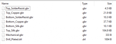
With the generous approval of Nelson, here you are,
the Gerber files of the PCB design in post #1286.
Patrick
.
Well! There's a project for the cnc engraver I just purchased... 🙂
Hi EUVL,
Are the mask layer and board outline included in the zip file as other names?
Got these errors at OSH Park:
couldn't find a mask layer.
can't find a board outline file.
Thanks.
Are the mask layer and board outline included in the zip file as other names?
Got these errors at OSH Park:
couldn't find a mask layer.
can't find a board outline file.
Thanks.
If you open the zip file youself, you will find 8 files required for the PCB.
It is obvious what they are supposed to mean.
Feel free to change the files names to suit your PCB shop.
As they are, they suit the shops we have used without problems, ever.
Cheers,
Patrick
.
It is obvious what they are supposed to mean.
Feel free to change the files names to suit your PCB shop.
As they are, they suit the shops we have used without problems, ever.
Cheers,
Patrick
.
Attachments
And same here - if anyone in Australia is chasing a pair of boards in a few weeks, please let me know!
Good to know that it is being put to use. 🙂
Please double check the PCB traces against schematics when soldering.
Just in case I cannot spot a stupid mistake somewhere, even though circuit is simple.
After all, you are the Alpha testers.
And first power up the amp with a lab supply with current limits set to 1.5A.
Happy soldering,
Patrick
Please double check the PCB traces against schematics when soldering.
Just in case I cannot spot a stupid mistake somewhere, even though circuit is simple.
After all, you are the Alpha testers.
And first power up the amp with a lab supply with current limits set to 1.5A.
Happy soldering,
Patrick
Hi Evul,
Sounds a plan - happy to feedback on the PCB when it arrives. I just need to work out the part numbers for the surface mount components. I see a CNY17-3 and I assume it's R6 there on the flip side; i just don't know the sizing and naming conventions for SMD parts.
...Just managed to get some of the opto's on ebay locally, and I guess it's time to bite the bullet on a SMD resistor pack!
Edit: I think I may take this to a separate thread so I don't take us too OT here...
Last edited:
For the SMD parts, IC1 can be e.g. CNY173SR2VM from On Semi.
Vishay equivalent will of course also do.
R6 can be any 1206 thin film, e.g. Beyschlag MMA02040C1000FB000 (MELF).
For C2, I would prefer a film cap, such as WIMA MKS2B051001N00JSSD.
But they are quite expensive from Mouser.
So you might want to use a electrolytic cap instead, e.g. Nichicon UKZ1H220MPM.
Patrick
just for variety sake , find enclosed few files
few years ago , one of Greedy Boyz contacted me for pcbs - Pa gratiously gave him all semis for J2 , same as nudge to pass me an order to make him set of pcbs
so , there it is , crudest and fastest and simplest I could do at moment , without too much things added ...... didn't go for miniaturization simply because SSouths need to be spread anyway ....... so - one sided pcb (that's why few shorties), use thick copper
FE made with 2SJ109 , use whatever you have in drawer (it's easier to put two 2SJ74 in pinout of 2SJ109 , than the other way 🙂 )
take Patrick's values
feel free to use it for your own pleasure
edit: in case of using IRFP outputs - change that trimpot to 1K or so ... or even better - cut trimpot trace and insert 680R in line
Attachments
Last edited:
And same here - if anyone in Australia is chasing a pair of boards in a few weeks, please let me know!
I'll put my hand up for a pair.
- Home
- Amplifiers
- Pass Labs
- FirstWatt J2