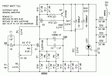
Is this 7 volt dependent on the supply voltage, i.e. with lower than the +-13.5 volt on the output this 7 volt lowers as well??
Very likely a not very smart question ....
I would like to use some Black gates BP that can handle 6,3 volt at the input that is why I ask it anyway
Thanks
Apparently ClarityCaps ESA film caps can be found in the Pass Labs XP-30 preamp, so that's what I used in the F1J. Why anyone would use decade old electrolytic caps, especially in that position (leakage current et al), really is beyond me.
https://www.diyaudio.com/community/threads/firstwatt-f1j.169509/page-6#post-5548052
Have them and just curious to compare the famous/old/horrible Blackgates with the green political correct BP of today. And maybe also the ClarityCap now you have mentioned them.
Just curious....
Just curious....
Hello to anyone who can help me, I would like to know if, in the F1J, the JFET IJW120R100T1 from INFINEON, would be suitable instead of the JFET SJEP120R100 from SemiSouth?
nope, Ugs )control voltage between source and gate) is substantially bigger in value
and .......SJEP is normally Off (enhanced) part
so control voltage is opposite in sign to
IJW which is Normally On (depletion) part
and .......SJEP is normally Off (enhanced) part
so control voltage is opposite in sign to
IJW which is Normally On (depletion) part
You could try with a separate bias voltage supply. The performance results with a different JFET may not be the same as with the SemiSouth.
For the F2J, omit the resistor R2. In its place provide a 12VDC power supply, connect V- to the pad that connects to the P1 pot, and connect the V+ to the board Ground. Adjust P1 to adjust the bias voltage to the JFET and JFET Vds. It works in theory.
The same can probably be done with the F1J except there are two FETs and more parts to deal with.
Since this is DIY, all is needed is someone bold enough to give it a try. 🤓
Attachments
- Home
- Amplifiers
- Pass Labs
- Firstwatt F1J
