SIT5 review on 6moons: https://6moons.com/audioreview_articles/firstwatt-sit5/
It's only the beginning and to be continued.
It's only the beginning and to be continued.

This is exciting news. I have a pair of Tokin SITs waiting for a project to build once a design is released—hopefully in the next year or so.
It does sound like the usual FW case is being used and how that is possible without some serious extra windage will be of interest.
Looking forward to seeing what kind of input stage will be used since we are told the output stage is a buffer.
Of course, it will be good but whether it is any "better" that what has been wrought by Ben Mah, Rahul and ZM remains to be heard.
Looking forward to seeing what kind of input stage will be used since we are told the output stage is a buffer.
Of course, it will be good but whether it is any "better" that what has been wrought by Ben Mah, Rahul and ZM remains to be heard.
Judging By the review they seem to be truely awesome amps. And they look good, inside out. But the true nerd soul in me gets really horribly tortured by the PICTURE of them very hot running true class A creations STACKED on top of each other.
I know. I know. They were not turned on on and probably not even connected to the mains ln that picture. But i still suffer greatly by just seeing pictures, visions, of such truely horrific SIT-torture.
🙂🙂🙂
I know. I know. They were not turned on on and probably not even connected to the mains ln that picture. But i still suffer greatly by just seeing pictures, visions, of such truely horrific SIT-torture.
🙂🙂🙂
OMG. Checked it again. The blue leds on the fronts are shining in BOTH channels…
Stacked.
”The horror, The horror!”

Stacked.
”The horror, The horror!”
Only thing missing is comparison to similar-class tube amps.
Steve Guttenberg contacted me about temporarily running them stacked, so I tested a pair that way and found the top one running at 3 degrees C higher, so at least it's not a short term reliability issue.

Only thing missing is comparison to similar-class tube amps.
I don't know if there is an equivalent tube amplifier (mu follower follower) available commercially.
Western Electric has the 91E, but its 300B is not a follower. It may be close to the SIT 4 though as the 300B is aided by a solid state "Steered Current Source".
Some interior shots at 6moons:https://6moons.com/audioreview_articles/firstwatt-sit5/2/
Looks like J313/K2013 for voltage amplification?
Looks like J313/K2013 for voltage amplification?
And of course, I'm just joshing around, but is that a multi-turn pot I see? 😱
That must be for setting the bias of the VAS stage. Without a lot of feedback, that could be a finicky adjustment.
^ Definitely! But Pa can nail that setting by just listening to the electrons and politely asking them to alter their flow.
Me... I pretty much stick to multi-turn pots.
OK.... back to discussing this incredible amp. I wanna hear it...
I always wonder how close our DIY amps get to the "real deal". I'll get a FW amp at some point.
Me... I pretty much stick to multi-turn pots.
OK.... back to discussing this incredible amp. I wanna hear it...
I always wonder how close our DIY amps get to the "real deal". I'll get a FW amp at some point.
Maybe something like this.....
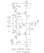
Gainstage the well known circuit from BA-3, no feedback, only heavy load resistors...
Nelson: " Loading the output of a gain element is less popular among amplifier designers, at least among those whose diagrams I peer at in the midnight hours. It is not popular largely because it reduces the gain without any other apparent benefit – just throwing away perfectly good gain that could otherwise be used for feedback. It conjures up the image of throwing away perfectly good food, and your mother would not approve.
We have a saying in my house (lifted from Cesar Milan) that “A tired puppy is a happy puppy.” It is my experience that sometimes you get subjectively better sound from a gain device which is operated at a significant portion of its capacity – not allowed to
loaf around with an easy job. We may find that it sounds better if we make it do some work.
There's nothing magic about this."
:--))
Gain around 18dB
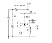
Outputstage like this, he showed in BAF 2022:
"Want more power? Using a P channel Mosfet we will make another version of the mu follower circuit which I call MUFF, for MU Follower Follower. It performs the same task as seen in the previous example, but takes its drive from the Source of the output device instead of the Drain. Works like glue.
R1 and R2 perform the same function as before and the voltage source is provided by an opto-isolator which senses the voltage across R1 + R2 so as to provide constant regulated DC current but variable AC.
The result is fairly spectacular. Now we are getting into the 30-40 watt power range for output power and even higher damping factor."
Of course only speculation......from my side.
:--))
I will do LTspice.
Gainstage the well known circuit from BA-3, no feedback, only heavy load resistors...
Nelson: " Loading the output of a gain element is less popular among amplifier designers, at least among those whose diagrams I peer at in the midnight hours. It is not popular largely because it reduces the gain without any other apparent benefit – just throwing away perfectly good gain that could otherwise be used for feedback. It conjures up the image of throwing away perfectly good food, and your mother would not approve.
We have a saying in my house (lifted from Cesar Milan) that “A tired puppy is a happy puppy.” It is my experience that sometimes you get subjectively better sound from a gain device which is operated at a significant portion of its capacity – not allowed to
loaf around with an easy job. We may find that it sounds better if we make it do some work.
There's nothing magic about this."
:--))
Gain around 18dB
Outputstage like this, he showed in BAF 2022:
"Want more power? Using a P channel Mosfet we will make another version of the mu follower circuit which I call MUFF, for MU Follower Follower. It performs the same task as seen in the previous example, but takes its drive from the Source of the output device instead of the Drain. Works like glue.
R1 and R2 perform the same function as before and the voltage source is provided by an opto-isolator which senses the voltage across R1 + R2 so as to provide constant regulated DC current but variable AC.
The result is fairly spectacular. Now we are getting into the 30-40 watt power range for output power and even higher damping factor."
Of course only speculation......from my side.
:--))
I will do LTspice.
Attachments
Last edited:
I keep a single turn trim pot under my bed pillow in hopes that a the First Watt fairy will come but that hasn't happened yet...^ Definitely! But Pa can nail that setting by just listening to the electrons and politely asking them to alter their flow.
Me... I pretty much stick to multi-turn pots.
I agree with Generg. Probably a BA3 with alterations, then the SE output involving some sort of optocoupler thing.
and may be he did this also.....
"Note that you can invert the power supply polarities on this particular circuit so that the Drain of the SIT is at ground and the Drain of the Mosfet is at V-, and in this way can avoid having power supply noise injected into the output, otherwise you need to have a quiet positive supply."
:--))
"Note that you can invert the power supply polarities on this particular circuit so that the Drain of the SIT is at ground and the Drain of the Mosfet is at V-, and in this way can avoid having power supply noise injected into the output, otherwise you need to have a quiet positive supply."
:--))
- Home
- Amplifiers
- Pass Labs
- First Watt SIT5