Here is an update to my post #1,913 above, which was about listening to a First Watt F7 I bought used. I mentioned that maybe I was hearing some of Nelson's famous second harmonic emphasis in the F7, in comparison to a class AB Denafrips setup. Today I was listening to one of the discussions on YouTube between Nelson and Steve Guttenberg, where they talked about the F7 in comparison to the SIT-3, J2, and F8. Part of discussion was about Nelson's long heritage of second harmonic emphasis going back to the beginnings of First Watt and beyond, BUT also how the F7 (and maybe the F5) was an exception to that being a third-harmonic type of amp. Well so much for my hearing prowess. 🙄
I really do like the F7 and it is living in my main system happily, with an ACP+ preamp. In contrast, the F7 was kind of plain sounding with the Denafrips Athena preamp, which by all accounts is a very good one, with very low measured distortion, and a very fancy volume relay setup, and a very fancy power supply chock full of regulators and capacitors.
Aha! Something the ACP+ is doing makes the overall sound more appealing. Also, it surely can't hurt having the headphone-capable single-ended IRFP610 output setup in the ACP+ giving some dynamic oomph to things. Maybe the second-harmonic character is coming in there? At any rate, another very interesting DIY lesson for me about circuit interactions, thanks to Nelson!

. . . how the F7 (and maybe the F5) was an exception to that being a third-harmonic type of amp.
I have found that F7 naturally has 2nd HD about 7-10db higher 3rd HD
FirstWatt F7 Owner's Manual
F7 is H2 dominant - roughly 10dB over H3

and if it matters, it is also negative phase H2

F7 is H2 dominant - roughly 10dB over H3
and if it matters, it is also negative phase H2
What is the difference between them (negative or positive) and how can it be detected by ear?negative phase H2
I won't even attempt to paraphrase or butcher any words from Nelson Pass on the subject of harmonic distortion. Here is a good place to start but by no means the end. Enjoy!
H2 Generator - Original Article
I can't seem to find any recording of Art Noxon from BAF2022 but I believe he had a viewpoint on whether or not people could distinguish between +/- phase H2.
I wouldn't worry about whether or not you could detect it unless you feel that it's consequential. It's more important to know which amps you like (and don't). If it so happens that the ones you do like are H2 dominant and you believe you prefer that, you can use that information to guide any future pursuits.
Correction, it wasn't Art Noxon in BAF2022. It was actual Steven Dear presenting at BAF2021 on Audio Perception
BAF 2021 videos
BAF 2021 videos
I believe that this meant that there was significantly higher H3 than other designs due to the push-pull nature of the F5 and F7. A properly implemented single-ended design will have very low levels of H3 compared to H2 when running at a similar bias point (one of my designs with bipolar outputs has about -40dB H3 compared to H2 in sim and about -30dB in a real circuit).the F7 (and maybe the F5) was an exception to that being a third-harmonic type of amp.
It is also possible, using P3 on F5/F7, to completely trim out the H2 component. I've always preferred the trimmer to be set so that H2 and H3 are roughly equal.
@twitchie - Yup, thanks, I'm familiar with that info from the owner's manual. In a number of places Nelson talks about the transition in some amps from primarily second harmonic distortion to more third harmonic as power output increases. In the YouTube video with Guttenberg the F7 seems to get clearly set aside from the general progression of First Watt designs. So overall I am not sure how this second vs. third picture for the F7 fits together, but it's interesting.
Nelson also refers to the ACP+ as basically a miniature J2 in his 2019 Burning Amp talk, and the First Watt article shows negative second harmonic distortion Hence my speculation that whatever the F7 may be doing, the ACP+ is in Nelson's negative-second-harmonic lineage.
Nelson also refers to the ACP+ as basically a miniature J2 in his 2019 Burning Amp talk, and the First Watt article shows negative second harmonic distortion Hence my speculation that whatever the F7 may be doing, the ACP+ is in Nelson's negative-second-harmonic lineage.
I still working on an F7 type amp that has two plateaus of OLG that looks something like this:

Recently, I added a Zobel network to the O/P shown in a simplified circuit here:

My motivation for adding this was that I have noticed that this kind of amp ( F5 / F7 ) has a tendency for some exagerated sibilance ( still there despite the fact that on my latest version there are only very small amounts of feedback 5k - 20k hz region. )
Regarding this sibilance, the zobel network was not particularly effective but it had a wonderfully positive subjective effect on midrange purity, imaging and reproduction of low level detail.
Anyone that has built an F7 / F5 type circuit might like to try adding a zobel across the amp O/P ( as close to the amp O/P as possible. ) and would be interested to hear if you notice the same subjective improvement.
If I succeed in taming the sibilance I am going to very happy with this F7 type amp.
If I do succeed I will post the final circuit here.
Recently, I added a Zobel network to the O/P shown in a simplified circuit here:
My motivation for adding this was that I have noticed that this kind of amp ( F5 / F7 ) has a tendency for some exagerated sibilance ( still there despite the fact that on my latest version there are only very small amounts of feedback 5k - 20k hz region. )
Regarding this sibilance, the zobel network was not particularly effective but it had a wonderfully positive subjective effect on midrange purity, imaging and reproduction of low level detail.
Anyone that has built an F7 / F5 type circuit might like to try adding a zobel across the amp O/P ( as close to the amp O/P as possible. ) and would be interested to hear if you notice the same subjective improvement.
If I succeed in taming the sibilance I am going to very happy with this F7 type amp.
If I do succeed I will post the final circuit here.
Last edited:
I have the clone F7 on sale - https://www.diyaudio.com/community/threads/f7-clone-fully-built-and-tested.406479/#post-7534739 if someone is interested in a perfectly matched Alfet transistors amp. Please ping me and I can negotiate to some extent.
Thanks
Thanks
Hey team, been working on a little F7 inspired derivative.... I have to say despite all of DIY projects, I have learned more without having all the answers than I have in a lot of DIYing "finished" or solved projects in the past.
I am having one small issue, perhaps overthinking, my heatsink temps from one channel to another, measured on the flat surface, just above the MOSFETs has discrepancy of about 2-4C with Bias set within 1-2mV - for example one might be at 179mV the other at 180mV with DC offset zero'd or close to it.
Sonically nothing I can pin so far (this is early power ups, still tuning) but just wanted to check in and see if there are any red flags.
What are the mosfets actually running at temperature wise? What insulators are you using? Are they tightened down the same?
Good notes Oreo - I will check tighetning - they are paired with keratherm style pads that have a better thermal conductivity rating as well as some really high conductivity paste. The tension/pressure may be the variable here.
Solid interfaces (mica, ceramic, etc.) work great with paste. The non electrically conductive soft interfaces (Keratherm, silpad, etc.) work with best with no paste.
What is the temp rise from heatsink and what percentage of that is the discrepancy? A small difference could be due to tolerances of the resistors the bias is measured from.
If you unmount the chips you can look at the impression left on the thermal pads to see what the contact area is, and it would be obvious if there was a high spot or something.
EDIT: You're using ceramic AND keratherm pads? The ceramic itself is an insulator so you only need thermal paste on both sides of the ceramic, this will give better results than pads. It will also be much more tolerant of debris and surface imperfections.
The W/mK rating is the heat conductivity of one cubic meter of insulator. So you have to translate that to the geometry of your insulator. I honestly haven't seen any real data on the real applied thermal conductivity of the ceramic insulators that are used by DIYers, but they are thicker than the Keratherm pads so the W/mK must also be better in order for them to be comparable. Given the same contact area, the ceramic has to have 26W/mK to be as good as the Keratherm. However 28W/mK according to WHO? Did anyone ever measure it?
Last edited:
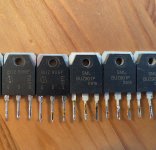
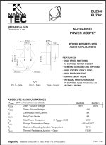
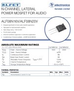
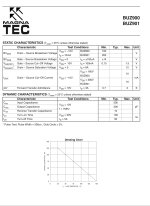
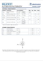
I just found that I have some BUZ 901p and 906p in my part bin. Looking at the data sheet, they look like they are the same part than the Alfet alf08n20v alf08p20v. Anyone having some experience with those? The F7 seem to be a good candidate to use them 🙂
Attachments
- Home
- Amplifiers
- Pass Labs
- First Watt F7 review