Good luck! 🙂
I presume you are aware of the existence of BC Robotics in Nanaimo? Link: BC Robotics Inc. - SparkFun, Adafruit, Raspberry Pi, and More! Located In Canada | Build Something Interesting
I know this place is robotics-oriented, but I bet they have wire, solder, tools, and a few other items that might be useful to you. I always forget something when I mail-order parts, and having a local store where you can pick up that one item you forgot might be very handy.
Are you planning to use the same colour (violet) wire for all connections? Using multiple colours makes it much easier to wire up circuitry, and enormously easier to fault-find, in case you have to do that.
(I should add that I've never done business with BC Robotics; I found it via a Google search a while ago.)
-Gnobuddy
Hey Gnobuddy,
I actually neglected to even remember that BC Robotics Inc. was in town. They will be an excellent resource for the small items that I probably forgot to include in my order. As for the violet wire, I do plan on using different wire colors for different connections ( I was just excited to get one of my favorite colors at such a good deal in bulk that I couldn't resist. ) I think I'll use the violet for the guitar signal path. We shall see how it goes.
Thanks,
John
Are you planning to use the same colour (violet) wire for all connections? Using multiple colours makes it much easier to wire up circuitry, and enormously easier to fault-find, in case you have to do that.
Sad news.....
🙂
🙁
Attachments
BAhahaha uh oh... It clearly states I can't use it! 🙂
Thanks,
That gave me a very good laugh. Perhaps I'll stick with the guidelines but substitute one of the colors with my precious violet!
Cheers,
John
Thanks,
That gave me a very good laugh. Perhaps I'll stick with the guidelines but substitute one of the colors with my precious violet!
Cheers,
John
As long as you use some 'system' for wiring, it will be a lot better than the 'all one colour' wiring projects that turn up here at diyaudio sometimes.
🙂
It makes troubleshooting a lot easier with a variety of colours for wires.
Also, when you are salvaging old tube radio/hifi/stereo units, you'll see that most of them use a logical wiring colour scheme, so it makes it a lot easier if you are trying to draw a schematic.
🙂
It makes troubleshooting a lot easier with a variety of colours for wires.
Also, when you are salvaging old tube radio/hifi/stereo units, you'll see that most of them use a logical wiring colour scheme, so it makes it a lot easier if you are trying to draw a schematic.
I didn't know there was an entire wiring colour code. But even as a boy, I noticed that the electronics I opened up always used red wire for the positive power supply rail, and black for ground / negative supply rail.Sad news...
So I've always used those two colours for those two purposes.
John is a rebel, he's going to use violet even though it's "not used"!
-Gnobuddy
I would think that would be white - "Above or below ground returns" according to the EIA chassis wiring colour code that VictoriaGuy posted.What colour for negative rails/bias?
This would be a bit of a re-think for me, if I were to switch to the EIA code. I've always used black for the most negative potential in the circuit. If that happens to be negative (below zero), then I typically use something like green or brown for the 0V / ground wiring.
Apparently I've been committing a variety of sins, according to that EIA table!
-Gnobuddy
according to the EIA chassis wiring colour code that VictoriaGuy posted.
That was originally a post by PRR; I grabbed it from a search result.
I've seen other wiring color codes online, but never bothered to see if they all specified the same colors for the same functions. I just looked, and they don't...
Good news, violet is used in some schemes! 🙂
Transformer and Wire Color Standards for Tube amps
DIY Audio Projects - Hi-Fi Blog for DIY Audiophiles: Tube Amplifier Wiring Color Code
I don't follow any scheme very precisely, but I do use red for B+ all the time.
I still find the blue and brown AC wiring colors from the European system completely mystifying. I could have done without that.
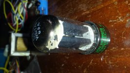
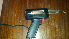
Got a few items today. Output transformer plus a few goodies. Rectifier tube last week. And I found a few analog testing devices this week plus a solder gun. More items to arrive shortly.
Going to have some fun soon!
Going to have some fun soon!
Attachments


Mmmmm.... Toys
I wanted some analog testing equipment and this stuff seemed pretty awesome. I'll put them to good use shortly. The old Weller Solder gun works great also gets hot very quickly. Was having fun practicing soldering to a chassis with it.
Just remember not to use the soldering gun to solder any semiconductors (silicon diodes and LED indicators, for instance), or any other heat sensitive or high-voltage sensitive components (small caps, electrolytic caps.)The old Weller Solder gun works great also gets hot very quickly.
Even contemporary thermoplastic-insulated wire can be damaged by the high temperatures a soldering gun can generate. If you smell hot stinky plastic when soldering wire ends, that's your clue that the soldering gun is doing damage. (I have even seen the overheated metal wire emerge completely through the melting surrounding insulation, making for a potentially unsafe situation if the wire is carrying high voltage.)
A soldering gun is to modern electronics what a 10 lb sledgehammer is to a carpenter - brutally effective, but completely lacking in finesse, and best used sparingly.
-Gnobuddy
A soldering gun is to modern electronics what a 10 lb sledgehammer is to a carpenter - brutally effective, but completely lacking in finesse, and best used sparingly.

I use my soldering gun infrequently.
Best use I've found for it is putting a cutting tip in it and using it to cut webbing and line for other DIY projects.
A 'big ole' iron with a heavy tip (a real sledgehammer!) is the thing to use if you need (want?) to solder directly to a chassis - it's not just the temperature, but the heat capacity of a heavy iron that's the key for that.
I recall paying $1 for my heavy iron at a ham swap meet - a great place to find/buy gear. Check your local ham radio club for dates - most clubs have a swap meet every year.
That's a real problem even with a good soldering setup - some of the insulation 'melts back' from the end quickly. It's handy to have heat shrink in different colours - I've had to 'repair' the end of a wire with damaged insulation a few times.Even contemporary thermoplastic-insulated wire can be damaged by the high temperatures a soldering gun can generate.
I find 'modern' (PVC?) insulation melts more easily than most of the 'vintage' wire I find in salvage projects, and the new stuff (including push-back wire) I buy from guitar amp suppliers like Hoffman.
I think a lot of builders use Teflon insulated wire because of the PVC melting problem. (?) The drawback with some Teflon wire is that the insulation is tough to strip, in my experience.
Using Teflon (PTFE, poly tetra fluoro ethylene) insulated wire at home is a very bad idea. 🙁...a lot of builders use Teflon insulated wire because of the PVC melting problem.
That quotation was taken from here: How Toxic is Teflon?...thermal degradation of PTFE leads to a litany of toxic compounds, including highly corrosive and lethal gases, and PFIB, a chemical warfare agent that is 10 times more lethal than phosgene (a chemical warfare agent used in WWI and WWII). These compounds persist in the environment and are not known to break down further.
In short, soldering Teflon-insulated wire heats the Teflon sufficiently to cause it to emit really, really nasty, extremely toxic fumes. This type of wire should only be soldered by people wearing serious protective gear, working in an environment that contains and disposes of the resulting toxic gases. Don't even think about using this stuff at home!
At one time I used Teflon-insulated wiring for circuitry that had to go into a vacuum tank. Teflon outgases much less than PVC, et cetera, so there was not much option. This was about thirty years ago. At the time, I had no idea just how toxic the stuff is once heated up to soldering temperature.
-Gnobuddy
I disagree.Using Teflon (PTFE, poly tetra fluoro ethylene) insulated wire at home is a very bad idea. 🙁
Teflon properties- see attached data from:
http://www.rjchase.com/ptfe_handbook.pdf
63/37 Pb/Sn solder melts at 183C or 361F
If I were working in an electronics sweatshop, soldering Teflon insulated wire 40 hours a week, without ventilation, I might worry about Teflon degradation- though flux fumes would probably be a more immediate concern.
I'm a hobbyist and probably only solder a few hours a year, total. Each joint takes a few seconds, and many don't involve wire insulation at all.
I do use a simple 'fume extractor' to move fumes away from my electronics bench.
Attachments
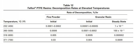
My soldering iron is set to either 700 F, or 750 F, depending on the thermal mass of the joint I'm soldering. Which is higher than the 650 F temperature above which PTFE breaks down, according to the document you referenced. 🙁63/37 Pb/Sn solder melts at 183C or 361F
I remember that of Teflon-insulated wire emitted quite a stench when I was soldering it 30 years ago, so some of the insulation certainly did get hot enough to break down and emit gases.
I understand the concept of free will, so let's agree to disagree at this point, and move on with trying to assist Jostenso22!
-Gnobuddy
No problem.I understand the concept of free will, so let's agree to disagree at this point, and move on with trying to assist Jostenso22!
🙂
You 'have your work cut out for you' here at diyaudio where the majority of recommendations for hookup wire seem to involve Teflon!
Start an educational thread on this, and sit back, and enjoy!
🙂
No, thank you! 😀<snip>
Start an educational thread on this, and sit back, and enjoy!
🙂
Like most people with an analytical mind and a technical background, I'm good at solving problems. But not at influencing people's opinions. Politics was never in the cards for me!
Case in point, there was a period when I flew electric-powered radio control model aircraft for fun. The battery connector of choice at my flying field had a number of negative qualities: it was heavy, expensive, had exposed contacts, was prone to short-circuit, required skilled soldering, and required so much disconnect force that delicate model aircraft were sometimes damaged in the attempt to unplug the battery.
I found an alternative connector that was lighter, cheaper, more reliable, had shrouded connectors, was longer lasting, easier to disconnect, and which could be soldered or crimped. It was so much better in every way that mattered, that after a short trial, I immediately switched all my model aircraft and battery packs over to it.
Other RC pilots noticed from time to time (usually when they wanted to borrow a battery pack!), and would ask me about the unfamiliar (to them) connector. I would then show it to them, and if they were curious, explain the reasons for my choice. This happened dozens of times over four years at that flying-field.
So how many other people switched connectors as a result? Zero! 🙂
-Gnobuddy
- Status
- Not open for further replies.
- Home
- Live Sound
- Instruments and Amps
- First Tube Amp Project