where does the factor 0.00002 in the param Kscale equation come from?
It is the reference pressure used to convert pressure in (N/m^2) to SPL(dB)
From the book "Acoustics" by Beranek, equation (1.18):
SPL(dB) = 20*LOG(P/Pref)
where:
P = sound pressure (N/m^2)
Pref = reference sound pressure = 0.00002 (N/m^2)
More details on using the Walker equations to get SPL on the "Notes" TAB of the spreadsheet posted here:
http://www.diyaudio.com/forums/planars-exotics/48120-experiences-esl-directivity-9.html#post2218526
Hi,
Thanks for SPICE project. The ESL_Seg program is a bit limited in capabilities(and especially because of no saving function).
Some questions :
1) How to change the model so parallel segmentation is possible? I have tried to edit the schematic but it seems to no longer work properly by just doing so. I guess it should be straight forward?
2) How to simulate off-axis response?
Regards,
Lukas.
So I finally have the PCB material. I got plenty of extra for experimentation. I'm getting some help for setting up the PCB machining and hopefully we can accurately perform the isolation routing as well as cutting the slots.
As a fallback, if neccesary, I am considering using a corner round end mill to place a 1/32" radius on the slot edges. Perhaps this is even better?
As a fallback, if neccesary, I am considering using a corner round end mill to place a 1/32" radius on the slot edges. Perhaps this is even better?
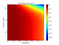
FYI, for those interested I wrote a python script to calculate the Polar response based on the JAES paper by golfnut. At the moment it only calculates and plots the Polar component.
I have the code mostly written to incorporate the on-axis response of the segmented panel and thus the SPL vs. Freq vs. Horizontal Angle. Attached is an example using my panel parameters (.889x.26m, 21 equally spaced segments, .0625" d-s spacing).
When I finish this I'll make it public. Don't expect a GUI for data entry. It will be config text files.
Attachments
1) How to change the model so parallel segmentation is possible? I have tried to edit the schematic but it seems to no longer work properly by just doing so. I guess it should be straight forward?
2) How to simulate off-axis response?
1) You can simulate any type of segmentation you would like with LTSpice just by changing the schematic and following the rules for plotting currents thru the segment capacitance. If after changing file names or the schematic the curves no longer show up on the response plot, you may need to add them. Just select current thru the segment of interest, then edit the curve data to multiply by "V(K)/sqrt(freq)".
Example LTSpice files and screen capture for a 3 segment parallel configuration attached.
Notice that the total current no longer flows thru R1. So, I needed to change the "total curve" to plot current thru the stator voltage source(V1)...which is probably what I should have used in the orginal 3-segment example.
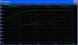
Also, I had some off-line questions concerning use of equal sized segments for the same overall panel size as the 3-segment ladder configuration from post#39. I figured it might be useful to post files of a 10-segment(equal size) design for comparison with the 3-segment(increasing size). An overlay comparing 3 & 10 segment also included.
2) Off-axis response involves summing current from the segments with appropriate time delays for segment location on panel for a given off-axis angle. I haven't found an easy way to do this in LTSpice. However, my Excel spreadsheet includes it. I'm not sure what the interest level is....perhaps I will have time during the upcoming holiday to clean it up for posting.
As before, you need to remove the "*.txt" suffix on the LTSpice files before using.
Attachments
-
 ESL_3seg_parallel_model.gif63.5 KB · Views: 326
 -
 ESL_10seg_model.gif75.7 KB · Views: 324
 -
ESL_3seg_parallel_model.asc.txt2.1 KB · Views: 88
-
ESL_3seg_parallel_model.plt.txt358 bytes · Views: 100
-
ESL_10seg_model.asc.txt4.5 KB · Views: 93
-
ESL_10seg_model.plt.txt606 bytes · Views: 93
-
 Overlay_3seg_vs_10seg.png672.4 KB · Views: 312
I used these tools to do my simulations of dispersions,
This seem to get moved around alot as the place it was last at is now defuct, If you can get them to download then I would suggest to do so before the disappear completely,
FRD Consortium
and these are great as well,
R&D-Team - Products
Here are the Sim's I did using the above,
http://www.esldiy.com/index.php?topic=95.msg212#msg212
http://www.esldiy.com/index.php?topic=95.msg217#msg217
http://www.esldiy.com/index.php?topic=95.msg218#msg218
FWIW
jer 🙂
P.S. The links to the FRD Consortium don't work, Hopefully they will come back sometime as they worked just a few months ago and I has posted the new link in another thread, I hope that I can still find the files in my archives!!! 🙁
Last edited:
Actually I did get this one to works which is the most important one and was the file I used to do my Sim's!!!
Yeahhh!!!
Asymmetrical Response Pattern Estimator
jer 🙂
Yeahhh!!!
Asymmetrical Response Pattern Estimator
jer 🙂
FYI, for those interested I wrote a python script to calculate the Polar response based on the JAES paper by golfnut. At the moment it only calculates and plots the Polar component...attached is an example using my panel parameters (.889x.26m, 21 equally spaced segments, .0625" d-s spacing).
Is your polar response based on the formulas(17 & 18?) in the JAES paper that assumes termination of the RC line with characteristic impedance? Or are you calculating it using summation of the output for each segment in the configuration you will build, which is probably unterminated. Just curious. The results are very similar, with the unterminated line adding a little flaring or bloom in the midrange at moderate(~30 deg) off-axis angles.
Oh, and I meant to ask before if you had checked what the bulk resistivity is for the PCB material you are using? Since you plan to have the copper facing away from the diaphragm, if the resistivity is too high, you may run into issues in low humidity conditions where charge collects on the inner surface of the PCB laminate resulting in loss of output.
Some info on this topic here: (wire ESLs are being discussed but the same principles hold for PCB stators)
http://www.diyaudio.com/forums/plan...truct-cube-louver-acoustat-7.html#post2154621
The graph that I posted is generated using equation 18. I have the code working for equation 17 as well, though. The calculation is marginally faster with 18 as there is no additional sub-loop for the summation during each iteration.
The PCB material is G10 (Garolite). Bulk resistivity is 6e6 MOhm-cm, surface resistivity is 1e6 MOhm.
The PCB material is G10 (Garolite). Bulk resistivity is 6e6 MOhm-cm, surface resistivity is 1e6 MOhm.
The PCB material is G10 (Garolite). Bulk resistivity is 6e6 MOhm-cm, surface resistivity is 1e6 MOhm.
That resistivity level is similar to most PVC insulation, so should work fine.
Hi,
Thanks for updated spice models. I compared the result to ESL_Seg. As you said, LTSpice model does not include proximity effect and form of SPL curve don't change depending on distance(which is expected).
My interest behind using LTSpice is to make a more accurate model, i.e including effects of wire-wire capacitance and such. Perhaps I could write a more advanced program than ESL_Seg in c++ but understanding of math has faded away over the years 🙁 .
So back to the model. I have tried to model a parallel capacitance with resistors bypassed with some capacitance. Can I just model it this way?
Too bad it's impossible to look at results off-axis.
Regards,
Lukas.
Attachments

My interest behind using LTSpice is to make a more accurate model, i.e including effects of wire-wire capacitance and such...I have tried to model a parallel capacitance with resistors bypassed with some capacitance. Can I just model it this way?
Too bad it's impossible to look at results off-axis.
By wire-to-wire capacitance, do you mean the small stray coupling capacitance between the adjacent segments?
If so, your model is incorrect as shown. Instead of the capacitors in parallel with the resistors there should be one capacitor between the top of C1 and C2, and another capacitor between the top of C2 & C3. I have measured values in the 20pF - 40pF range for capacitive coupling between PVC wire stator segments.
Just curious, why are you interested in using the parallel configuration rather than the ladder configuration? The ladder network does a much better job at removing HF content from the outer panel segments.
Hi,
Yes you are right. What was I thinking while drawing the schematic? Perhaps girls ? Heck the world is a place where one must chose between ESL and those 😀
My measurements regarding to wire-wire capacitance are very similar as yours. It's ~20pF per meter of length when wires are spaced 1mm apart. It becomes somewhat of concern when high values of resistance are used(>> 150K). In practice it can make a difference of few db off-axis depending on angle. Therefore model with large amount of segments may show better behavior off axis in real world despite contrary result while simulating.
I understand that series resistor ladder makes a steeper filter. However in some certain configurations with small amount of sections parallel ladder gives a more linear behavior off-axis. Just curious if that's a real thing or an artifact of ESL_Seg_ui. Perhaps it would be the best to solder and test.
Cheers
Lukas.
Yes you are right. What was I thinking while drawing the schematic? Perhaps girls
? Heck the world is a place where one must chose between ESL and those 😀My measurements regarding to wire-wire capacitance are very similar as yours. It's ~20pF per meter of length when wires are spaced 1mm apart. It becomes somewhat of concern when high values of resistance are used(>> 150K). In practice it can make a difference of few db off-axis depending on angle. Therefore model with large amount of segments may show better behavior off axis in real world despite contrary result while simulating.
I understand that series resistor ladder makes a steeper filter. However in some certain configurations with small amount of sections parallel ladder gives a more linear behavior off-axis. Just curious if that's a real thing or an artifact of ESL_Seg_ui. Perhaps it would be the best to solder and test.
Cheers
Lukas.
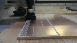
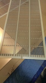
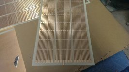
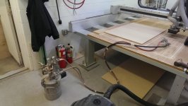
Stators are fully machined. They seem to be pretty good. The machine was accurate enough to take off about .002" just to remove the copper, and also accurate enough to remove about .008" of Cu around each slot. I made these by machining flat a piece of MDF. Then I glued the copper clad G10 to the MDF. The flatness was pretty good (within about .001"). I used a shop vac for chip removal since Garolite is nasty stuff and it would get into the dust collection system. I used a 1/8" 4-flute end mill. It was dull about 3/4 of the way through the second pair. The G10 milled fine with the dull bit but the Cu got messy. I need to clean it up with some sandpaper. Pics attached
Attachments
Hi,
nice try so far.
Will there be any additional etching process?
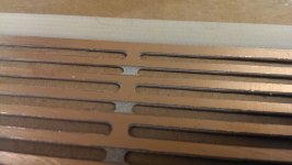
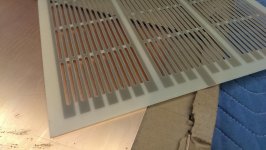
It'd be good if the copper recessed a bit from the hole rims and if the ends of the copper strips at the top and bottom rim of the stator plate could be rounded instead of square-cut. Sharp edges are always prone to flashover.
jauu
Calvin
nice try so far.
Will there be any additional etching process?
It'd be good if the copper recessed a bit from the hole rims and if the ends of the copper strips at the top and bottom rim of the stator plate could be rounded instead of square-cut. Sharp edges are always prone to flashover.
jauu
Calvin
I will not be doing any etching. In fact these have not been etched at all. It is purely the result of machining.
At the moment the copper is recessed about .008" from he slot edges. I will manually sand all of these to more of a chamfer though as I'm not quite satisfied with that amount.
Regarding the sharp edges, I am planning on having the copper face out, so I can't imagine that I'll get any arcing from those corners.
Hi,
in the interest of highest efficiency -and that is THE ESL mantra- it´d be good to have the copper layer facing toward the diaphragm. This is also quite positive regarding safety aspects.
In theory, the ´inward´ facing copper layer wouldn´t need any insulation at all, if the diaphragm featurs a very high resistivity coating.
A thin layer of acrylic or PU is all what is needed to encapsulate the copper to prevent corrosion.
You won´t prevent arcing from a stator to the membrane with any thin insulation anyway. Just crank up the volume. The only way to prevent that, would be a very thick, high-epsilon stator after Beveridge.
So, if You can´t prevent flashovers the use a very thin insulation layer to keep efficiency high.
jauu
Calvin
Agreed. My Excel spreadsheet modeler includes ability to model segment-to-segment capacitance as well as transformer parasitics.My measurements regarding to wire-wire capacitance are very similar as yours. It's ~20pF per meter of length when wires are spaced 1mm apart. It becomes somewhat of concern when high values of resistance are used(>> 150K).
Just back from vacation, hopefully in the next week or so I can clean up a copy to post for people to try.
Interesting...I have no reason to believe the modeling of parallel configuration in ESL_Seg_ui is flawed, although I haven't down extensive checking. Certainly the ladder configuration matches well with other modeling techniques and the AES paper.I understand that series resistor ladder makes a steeper filter. However in some certain configurations with small amount of sections parallel ladder gives a more linear behavior off-axis. Just curious if that's a real thing or an artifact of ESL_Seg_ui.
Perhaps I will see about including a parallel configuration option in my spreadsheet, for completeness.
- Status
- Not open for further replies.
- Home
- Loudspeakers
- Planars & Exotics
- First time ESL builder