

i would just get them working.
Agree with Adamus here,
I did use resistors but that was because I hadn't got all the parts to finish the bias blocks and the ccs, plus the rest of the parts were scored very cheaply off Ebay and none of the parts apart from the OT's were known to be good.
Also I liked the sound so much I got lazy and it was weeks before it was properly finished. Another reason to push on.
Particularly liked the ccs on the LTP.
")
Last edited:
Ok, I changed the polarity of the LED on the LTP CSS and now it is lighting up. I tested all of the circuits again and here is what I got. I tested both bias blocks at twelve volts with a 330 ohm load and measured 28 and 30 mA for the two blocks. The LTP CCS was tested at twelve volts and a 20K ohm load and measures .21mA. Do these numbers sound reasonable, or do you think I have a problem?
Thanks for the help guys,
-Matt
Thanks for the help guys,
-Matt
The diffamp CCS passes 1.0 mA for 500uA per side
Taken from post 147 of baby huey thread
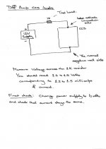
To test the diff amp current sources hook them up to the -15V supply you made and connect a dummy load of say 4K7 from the upper transistor cathode to 0V. Then check that you are developing approx 4.7V across the 4K7 (that is approx 1mA through the 4K7 dummy load).
Using a 20k resistor instead of 4K7 might have increased the error, have you anything smaller
Last edited:
Now I'm really confused, I don't know if the circuits are working or not. Theoretically, how would I go about eliminating the solid state blocks from the circuit. I want to get this amp running, but with final exams and my senior design project deadline coming up, I don't have the time to re-make these circuits and possibly still not have them work.
More pictures, scribbled during lunch break.
Hope these help,
Ian
Ok, on your diagram it looks like the CCS has only two wires, mine has four. There's two that attach to the 6.3 volt tap on the transformer, then I have a wire attached to the point on the schematic labeled 0v and one at the point labeled CCS. Is this right or did I make a mistake following the schematic?
OK - so you have combined the -ve supply and the CCS on one board.
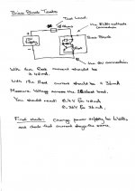
Looking at the original schematic:
Leave your 2 wires going to the heater winding disconnected.
Wire the 12V supply +ve to +ve of the 47uF electrolytic
Wire the 12V supply -ve to -ve of the 47uF electrolytic
Wire the 1K test load resistor between CCS#1 connection and 12V supply +ve
Measure the voltage across the 1K test load.
You should see 1.2 to 1.6 volts.
Lower power supply voltage to 6V and re-measure the voltage across the 1K test load - it should be the same as it was before (within a few percent).
Cheers,
Ian
Last edited:
Then you have a problem with the CCS, it is not working properly - either you have wired one or both of the transistors wrongly, they are the wrong type (PNP instead of NPN) or they are cactus (as in blown up).
For fault finding:
1) make sure the LED is ON - if not check that its wired the correct way round. (Also check that you have connected the power supply the correct way)
2) remove the top transistor and take the CCS#1 from the collector of the bottom transistor. Get that working as a constant current source first. Once that works, add the top transistor back in.
Why? The bottom transistor and the LED make up the Constant Current Source (CCS), so make that work first. The top transistor (what is called cascode connection)is there just to improve the performance of the CCS.
Cheers,
Ian
More pictures, scribbled during lunch break.
Hope these help,
Ian
I just checked the bias blocks using the method you showed in the diagram and they both read .4v at 12v applied and .38 volts when I dropped the supply to six volts. I think this means that the bias blocks are working, so all I have to do is figure out the CCS circuit.
Ok, I found an error in my testing method when I first tested the CCS, I did it again and read 1.54 volts when I supplied 12v and 1.36 volts when I dropped the supply to six volts. How do these numbers sound? Also, I think I figured out my question about the capacitor. Is it connected in what appears to be reverse polarity because the supply is supplying a negative voltage?
yes that is why the cap is that way round.
the numbers sounds like its working to me. you will get funny readings at 6v, there isnt enough V over the CCS for it to work propoerly.
to check, change the 1k to 330r or something near there, check again at 12v and the result should be identical (using ohms law)
the numbers sounds like its working to me. you will get funny readings at 6v, there isnt enough V over the CCS for it to work propoerly.
to check, change the 1k to 330r or something near there, check again at 12v and the result should be identical (using ohms law)
Last edited:
New Test shows that the Diff Amp CCS is working too. Sorry about tardy reply - I had a proxy server (Perth, Western Australia) interruptus experience and was too lazy to reconfigure to our New York proxy (Actually I have only default permissions on the New York proxy which means I'm blocked from DIYAudio) . Back up now.
BH should be full steam ahead!!!
Cheers,
Ian
BH should be full steam ahead!!!
Cheers,
Ian
Well, I've started with the wiring, and I have the power supply section done. With no load I measure 280 volts on the high voltage supply, I was expecting 320. Is 280 volts going to be a problem?
An externally hosted image should be here but it was not working when we last tested it.
An externally hosted image should be here but it was not working when we last tested it.
- Status
- This old topic is closed. If you want to reopen this topic, contact a moderator using the "Report Post" button.
- Home
- Amplifiers
- Tubes / Valves
- First time baby Huey amplifier build