Hey all, I'd like some feedback on an amplifier I'm building. This is my first time semi-designing an amp, so it would be really helpful for me to have more experienced eyes look at it. Buckle up, this is going to be a lengthy post.
Originally, I was going to build an amplifier based on the schematic shown here: DHTRob - EL3N Single Ended Sakuma style. It uses EL3N tubes as both drivers and output tubes. But the more I researched, the more I went down the "what if" rabbit hole, and have reached the heavily modified design I have now. I have a bunch of changes to the original schematic from that url. Some of them may or may not be good ideas. I'm still learning a lot as I go, so I'm open to constructive criticism.
The ultimate goal with this project is two things:
Gyrator loaded with anode voltage set at 150V.
Biased at -4V (2 green LEDs?)
- 6J5 driver will draw about 6mA
- EL3N driver will draw about 17.5mA
Output tubes:
Will have a switch for the cathode resistor to switch between EL3N and other output tubes as well as the HT value. I'm hoping I can implement one switch that switches both of those things at the same time.
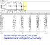
EL3N
- plate voltage: 275V
- bias voltage: -9.8V
- bias current: 20mA
- cathode resistor: 490 ohms
- Total amp draw: ~75mA (20 + 20 (outputs) + 17.5 + 17.5 (drivers))
Every other output tube (256 ohm cathode resistor):
I designed these with the EL34 as a baseline. So the specs are correct for that tube. The others will vary a bit with plate voltage and bias current than what's shown here because if certain output tubes draw more current with a 256 ohm cathode resistor, the B+ will go down... and if they draw less current, the B+ will go up. This will in-turn affect how much current is drawn (I think!). I'm hoping that I found a happy-enough medium with the 256 ohm cathode resistor that the B+ variations between these output tubes will be acceptable. The only tube I'm a little worried about is the KT88. I might raise the cathode resistor to bring down currents a bit to get the KT88 in maybe the ~80mA range.
EL34
- plate voltage: 275V
- bias voltage: -18V
- bias current: 70mA
- cathode resistor: 256 ohms
- Total amp draw: ~156mA (70 + 70 (outputs) + (6 + 6 (6J5 drivers)))
KT66
- plate voltage: ~275V
- bias voltage: -18.69V
- bias current: 73mA
- cathode resistor: 256 ohms
KT77
- plate voltage: ~275V
- bias voltage: -15.37V
- bias current: 60mA
- cathode resistor: 256 ohms
KT88
- plate voltage: ~275V
- bias voltage: -23.89V
- bias current: 90mA
- cathode resistor: 256 ohms
6L6GC
- plate voltage: ~275V
- bias voltage: -17.65V
- bias current: 68mA
- cathode resistor: 256 ohms
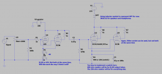
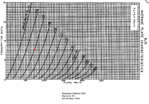
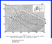
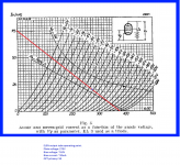
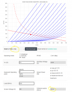
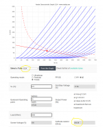
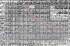
Attached are pictures of the schematic, some of the load lines and operating points for input/output tubes, and an example of a PSU. Again, I'm still kinda new to all this, and there's no way I got everything right on this first try. Any and all comments/suggestions are welcome.
Outstanding questions:
- The Valve Wizard -Push-Pull At the bottom. Though this is for push-pull, and I don't know if it's applicable to SET amps.
- There's also a power estimate on the universal loadline calculator I used, but the power from that is way higher than the previous two. Not sure if any of these are accurate estimates.
Originally, I was going to build an amplifier based on the schematic shown here: DHTRob - EL3N Single Ended Sakuma style. It uses EL3N tubes as both drivers and output tubes. But the more I researched, the more I went down the "what if" rabbit hole, and have reached the heavily modified design I have now. I have a bunch of changes to the original schematic from that url. Some of them may or may not be good ideas. I'm still learning a lot as I go, so I'm open to constructive criticism.
The ultimate goal with this project is two things:
- To have an all-EL3N amplifier like the design from DHTRob above.
- Be able to replace my Ampsandsound Mogwai SE by being able to roll the output tubes from that amplifier (EL34, 6L6GC, KTxx family, etc)
- Able to roll 6J5 drivers instead of EL3N drivers.
- Able to roll EL34/6L6GC/KTxx tubes as output tubes instead of EL3N.
- Gyrator loaded input tubes for better support of 6J5. As far as I understand it, I can set the anode voltage with a gyrator. Therefore, I can set the anode voltage to 150 and bias at -4V. This should provide a happy operating point for both EL3N and 6J5 drivers.
- One chassis design rather than separate PSU.
- Switch to change cathode resistor for EL3N outputs and other output tubes (explained more below). Switch may also have to switch between different HV secondaries from the PT due to the way lower current that EL3N output tubes operate at.
- Primarily for headphones. I almost exclusively listen to headphones, but I may also provide speaker outs.
- OPTs: Custom made 5K:8/16/32. 32 ohm secondary will be used for the headphone jack.
- PT: HV secondary will have to be custom if I want to support EL3N output tubes. The current draw in an EL3N-output configuration will be much lower than the other potential output tubes (20mA per EL3N output tube vs ~70mA for others), meaning my resulting B+ will be higher. So something like a 0-320-360V secondary with a switch to switch between 320V and 360V can accomodate that.
- Current schematic: pic attached.
- LCLCRC PSU for low ripple when using headphones (pic attached).
- This will be a (almost) no expense spared kind of project. So I'm looking at custom made Monolith Magnetics transformers for this project.
- Target B+: ~275V
Gyrator loaded with anode voltage set at 150V.
Biased at -4V (2 green LEDs?)
- 6J5 driver will draw about 6mA
- EL3N driver will draw about 17.5mA
Output tubes:
Will have a switch for the cathode resistor to switch between EL3N and other output tubes as well as the HT value. I'm hoping I can implement one switch that switches both of those things at the same time.
EL3N
- plate voltage: 275V
- bias voltage: -9.8V
- bias current: 20mA
- cathode resistor: 490 ohms
- Total amp draw: ~75mA (20 + 20 (outputs) + 17.5 + 17.5 (drivers))
Every other output tube (256 ohm cathode resistor):
I designed these with the EL34 as a baseline. So the specs are correct for that tube. The others will vary a bit with plate voltage and bias current than what's shown here because if certain output tubes draw more current with a 256 ohm cathode resistor, the B+ will go down... and if they draw less current, the B+ will go up. This will in-turn affect how much current is drawn (I think!). I'm hoping that I found a happy-enough medium with the 256 ohm cathode resistor that the B+ variations between these output tubes will be acceptable. The only tube I'm a little worried about is the KT88. I might raise the cathode resistor to bring down currents a bit to get the KT88 in maybe the ~80mA range.
EL34
- plate voltage: 275V
- bias voltage: -18V
- bias current: 70mA
- cathode resistor: 256 ohms
- Total amp draw: ~156mA (70 + 70 (outputs) + (6 + 6 (6J5 drivers)))
KT66
- plate voltage: ~275V
- bias voltage: -18.69V
- bias current: 73mA
- cathode resistor: 256 ohms
KT77
- plate voltage: ~275V
- bias voltage: -15.37V
- bias current: 60mA
- cathode resistor: 256 ohms
KT88
- plate voltage: ~275V
- bias voltage: -23.89V
- bias current: 90mA
- cathode resistor: 256 ohms
6L6GC
- plate voltage: ~275V
- bias voltage: -17.65V
- bias current: 68mA
- cathode resistor: 256 ohms
Attached are pictures of the schematic, some of the load lines and operating points for input/output tubes, and an example of a PSU. Again, I'm still kinda new to all this, and there's no way I got everything right on this first try. Any and all comments/suggestions are welcome.
Outstanding questions:
- Is a 6J5 or EL3N enough to drive potential power tubes like EL34 or KTxx tubes?
- Considering my size limit for this amp: I have room for either a tube rectifier (I like the aesthetic) or a potted choke for choke input PSU. Is a choke input PSU superior enough to cap input PSU to justify having?
- Is there any way to estimate the output power this amp will have? I found a couple formulas for output power, and I don't know if any of these are accurate:
- The Valve Wizard -Push-Pull At the bottom. Though this is for push-pull, and I don't know if it's applicable to SET amps.
- There's also a power estimate on the universal loadline calculator I used, but the power from that is way higher than the previous two. Not sure if any of these are accurate estimates.
Attachments
Before you even start, if you are insistent on using EL3N valves, make sure you can actually get enough of them. They are an old and well-superseded tube.
If you want to be able to tube-roll EL34/6L6 types, then start your design around them.
If you want to be able to tube-roll EL34/6L6 types, then start your design around them.
Other things to note:
EL3N tubes come in either 8SC or A08 bases. You other tube choices are all A08.
EL3N was superseded by EL33 in A08 base. They have similar output to 6V6, in triode you will see a whole 1 to 1.5 watts.
EL3N tubes come in either 8SC or A08 bases. You other tube choices are all A08.
EL3N was superseded by EL33 in A08 base. They have similar output to 6V6, in triode you will see a whole 1 to 1.5 watts.
Thanks for the input. I have a nice stash of never-used Phillips EL3N tubes with the 8SC base. I already have sockets for them as well. I was planning on having both types of sockets in the amp to avoid adapters.
The low output power from them doesn't bother me so much, as this amp will mostly be used for headphones.
The low output power from them doesn't bother me so much, as this amp will mostly be used for headphones.
I would look at the power supply and how the amp starts up and shuts down (if large caps).
The grid is likely to see a voltage before the bias of the tube and it's not guaranteed in which order that will occur (dependent on each tube's individual state and age). An anode connected OPT is going to see current as the tube comes up (with the grid being 0 or positive) until the system is all up and running.
Although probably not a problem for tubes as such on start..I assume there's muting to protect the headphones?
Edit. I see R3.. ok that should help the startup.
Last edited:
I've used the EL33 quite a lot. It's an updated EL3n as you know. It's a full, rich sound with plenty of detail. A nice tube. EL11 is an alternative - a bit leaner. If you can stand a top cap I prefer EL38 as an output tube. The EL38 is a really good tube and I prefer it to the EL12. I have a bunch of all these tubes. I've tried EL33 into EL38 and I'm very happy with that combination. I hate side contact bases - you have to prise the tubes out with 2 screwdrivers. A lot of the tubes end up with loose bases. Terrible design.
You say "Able to roll EL34/6L6GC/KTxx tubes as output tubes..." I certainly prefer the EL38 to any of those.
As for 6J5GT I haven't compared it directly to the EL33. In 6J5GT variants I like the 2C22/7193 best if you can deal with 2 top caps. The 6P5 is nice too. I suspect the EL33 is as good as those. I also preferred the EL33 to KT61, KT81 which were close in sound, and also to 6V6 or EL84.
I should just add that I used all of the above tubes in triode. I should also add that the EL33 and EL38 both need 5K OPTs. If you have 4 and 8 ohm taps on the 3.5K OPT I'd try it on the 4 ohm tap. That's what I did in my EL38 amp.
.
Last edited:

I would look at the power supply and how the amp starts up and shuts down (if large caps).
The grid is likely to see a voltage before the bias of the tube and it's not guaranteed in which order that will occur (dependent on each tube's individual state and age). An anode connected OPT is going to see current as the tube comes up (with the grid being 0 or positive) until the system is all up and running.
Although probably not a problem for tubes as such on start..I assume there's muting to protect the headphones?
Edit. I see R3.. ok that should help the startup.
Thanks for the heads-up. I will include other protections for headphones and output transformers too. I like to follow a procedure when using headphones. I'll turn on the amp while the headphones are unplugged, then plug them in after the tubes have warmed up. I also unplug them before I turn the amp off.
I like to use switched headphone jacks with resistors going from L and R to ground so when no headphones are plugged in, the OPT still has a load. Then when headphones are inserted, the resistors are switched out of the circuit and the headphone becomes the load.
I've used the EL33 quite a lot. It's an updated EL3n as you know. It's a full, rich sound with plenty of detail. A nice tube. EL11 is an alternative - a bit leaner. If you can stand a top cap I prefer EL38 as an output tube. The EL38 is a really good tube and I prefer it to the EL12. I have a bunch of all these tubes. I've tried EL33 into EL38 and I'm very happy with that combination. I hate side contact bases - you have to prise the tubes out with 2 screwdrivers. A lot of the tubes end up with loose bases. Terrible design.
You say "Able to roll EL34/6L6GC/KTxx tubes as output tubes..." I certainly prefer the EL38 to any of those.
As for 6J5GT I haven't compared it directly to the EL33. In 6J5GT variants I like the 2C22/7193 best if you can deal with 2 top caps. The 6P5 is nice too. I suspect the EL33 is as good as those. I also preferred the EL33 to KT61, KT81 which were close in sound, and also to 6V6 or EL84.
I should just add that I used all of the above tubes in triode. I should also add that the EL33 and EL38 both need 5K OPTs. If you have 4 and 8 ohm taps on the 3.5K OPT I'd try it on the 4 ohm tap. That's what I did in my EL38 amp.
.
I will definitely look into those tube alternatives! I don't mind top caps at all either. The reason for my current tube choices is that I wanted to use tubes I already have. As for my OPT, it is 5K, not 3.5K. So I'm good there! I will also be running all of these tubes in triode mode. I hear triode mode sounds better, and I don't need the extra power of pentode mode anyway.
I appreciate the comments so far. Does anyone have any comments or concerns regarding any of the following:
- Chosen operating points or load lines.
- Is a 6J5 or EL3N enough to drive potential output tubes like EL34 or KTxx at my current operating points?
- How to estimate power output with a specific tube set.
- Any other glaring flaws or oversights on my part?
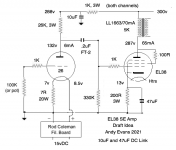
Here's an idea for you. I've departed a bit from your initial concept, but this design uses a 5K SE OPT and an ELxx output tube. By using the EL38 we have enough gain to use a 26 in the driver position. This makes a big difference to the sound.
I spent all of 2020 working on two different projects - an EL38 amp with a DHT driver and a 300b amp with an indirectly heated driver. in both cases one of the tubes was a DHT and it was fascinating to compare the results. The 26 as driver sounded better than an 01A which at lower current sounded a bit lean, though beautifully detailed. The 26 was just right and had that special magic on voices it's noted for. With the right driver, the 300b was excellent. It was pretty much a dead heat between the 2 amps - both were wonderful to my ears (and my wife who sat in on listening sessions). I mention this particular amp because for a while it had an EL33 driver before I switched to a 26. The voltages should be in the ball park, and might vary with the individual tubes used.
The design only sounds this good with Rod Coleman regs (Lyrima UK) on the 26 and DC link caps, so don't be tempted to alter these or the Russian teflon coupling caps (2x 0.1 FT-2). You will change the voicing, which has been developed over several A-B tests to bring out the best timbre to acoustic instruments and voices. By all means experiment later, but start with the parts shown. I just drew up this design, so please point out any slips I may have made. Note that the 26 is in filament bias - not conventional self bias.
Attachments
Last edited:
Interesting. I hadn't really considered the use of DHT driver tubes. I'll let that idea marinate for a bit while I continue designing. Thanks for the suggestion!
Quick question: Let's say I end up with a configuration that has both octal and 8SC output sockets in parallel (Where one or the other socket is used like in the schematic in post 1). Let's say I'm currently using tubes in the octal sockets and the 8SC sockets are empty. How dangerous would those empty 8SC socket be? Because it's pretty easy to accidentally stick a finger in those side-contact 8SC sockets.
I've seen another amp that has a similar output tube configuration recently, and it didn't look like there was any switch to turn off sockets that aren't used. That seems dangerous to me, especially with the 8SC sockets.
Would it be advisable to have a switch that turns off voltage (B+ and heaters) to these 8SC sockets when not in use?
I was wondering the same thing with side contact sockets, but with regard to rectifiers where you could use one AZ4 or two AZ1. My best guess was to screw the unused socket in upwards from the bottom and leave a length of screw on both sides. You could then make a plate from 1mm or 2mm aluminium that fitted over the socket when unused and screw it onto the screw threads sticking up.
> How dangerous would.....
YOU know better. Do you trust yourself?
It is your lover/child/dog/cat. Are they likely to get zapped?
Around here: no children, the other adult human does not stick fingers in electricals.... but once we had a dog's brass tag hit the small exposed metal on a US-type 110V plug (there was a food crumb behind it). So up off the floor I am not too concerned, but down around dog-nose and below I try to be careful.
At work I've had exposed 600V with little supervision for years. But everybody was afraid to come in my shop.
Good question. I'm actually in the process of learning LTspice and haven't done bode blots yet. If you have any pointers in terms of sim parameters or where to measure, I'm all ears.
Good question. I'm actually in the process of learning LTspice and haven't done bode blots yet. If you have any pointers in terms of sim parameters or where to measure, I'm all ears.
Sure.
Instead of the .trans use ".ac dec 10 10 100K" for example.
Then change the input signal to simply be "AC 1" for example.
Try without any negative feedback first, then add that in later. Clicking around you can see where there's issues with miller capacitances, capacitors etc etc.

The main point is look at miller capacitance as an example - perhaps look at a cascode and "cascode bandwidth" or "cascode bode plot" as this will introduce to you the concepts w.r.t tubes etc and be something that's relatable to tube amps. I'm not an expert simply I found that if I had a model it pointed out some weaknesses with the design that I could then look at solving.
Last edited:
You already put the schematic in LTSpice, just finish it to get power output.I appreciate the comments so far. Does anyone have any comments or concerns regarding any of the following:
- Chosen operating points or load lines.
- Is a 6J5 or EL3N enough to drive potential output tubes like EL34 or KTxx at my current operating points?
- How to estimate power output with a specific tube set.
- Any other glaring flaws or oversights on my part?
Sure.
Instead of the .trans use ".ac dec 10 10 100K" for example.
Then change the input signal to simply be "AC 1" for example.
Try without any negative feedback first, then add that in later. Clicking around you can see where there's issues with miller capacitances, capacitors etc etc.
Thanks for the pointers. I'll do some experimenting this weekend.
You already put the schematic in LTSpice, just finish it to get power output.
Very true. I'm still working on ramping up my LTspice knowledge and getting tube models set up properly.
- Home
- Amplifiers
- Tubes / Valves
- First time amplifier design help, critique, and suggestions