Spent this last weekend learning some ltspice. This tool is incredible! There's so much functionality packed into here. Here's some observations I found:
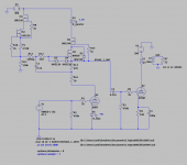
1. I have a working updated schematic with the gyrator load on the input tube. I used the 6SN7 as a placeholder because I don't have models for 6J5 or EL33. I used a triode connected KT88 as the output tube for now. For all the mosfets in the gyrator, I'm at the mercy of the models I found online. I don't know how accurate they are. Interestingly, I have higher distortion figures using the gyrator vs using a simple resistor load. But there's a chance I didn't do everything quite right or the models aren't perfect.
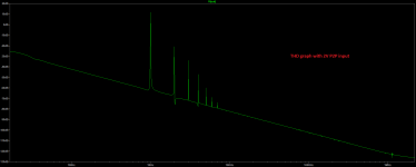
2. I generated a bode plot from the secondary of the output transformer, and I'm not really sure how to interpret it. It doesn't look like a normal frequency response graph. Am I measuring in the correct place?
3. I ramped up the voltage on the input to 3V (6V peak-to-peak) just to see what happens. I saw that the output voltage was cut off on one end of the sine wave. I realized that this is clipping! I was able to play around with output tube bias points and see the effects on how much output voltage I can achieve before clipping. I feel like I'm learning so much by playing around with ltspice. It's pretty fun.
Here are some figures from playing around with it:
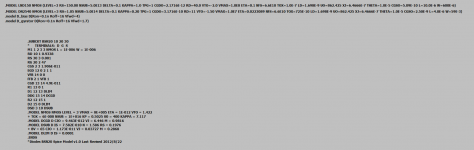
2V peak-to-peak: 2.4% distortion and 10.5V P2P output
RMS output = 10.5/(sqrt(2)) = 7.42V RMS
Watts into 32 ohm headphones: (7.42^2)/32 = 1.7W
0.16V peak-to-peak input: 0.16% distortion and 0.81V P2P output
RMS output = 0.81/(sqrt(2)) = 0.57V RMS
Watts into 32 ohm headphones: (0.57^2)/32 = 10mW. Considering most headphones are 90-100db/1mW, that's still overkill for power. But distortion is very low at this level.
I don't have models for some of the tubes I'm interested in (26, EL33, EL38), but results so far with the models I have look promising!
1. I have a working updated schematic with the gyrator load on the input tube. I used the 6SN7 as a placeholder because I don't have models for 6J5 or EL33. I used a triode connected KT88 as the output tube for now. For all the mosfets in the gyrator, I'm at the mercy of the models I found online. I don't know how accurate they are. Interestingly, I have higher distortion figures using the gyrator vs using a simple resistor load. But there's a chance I didn't do everything quite right or the models aren't perfect.
2. I generated a bode plot from the secondary of the output transformer, and I'm not really sure how to interpret it. It doesn't look like a normal frequency response graph. Am I measuring in the correct place?
3. I ramped up the voltage on the input to 3V (6V peak-to-peak) just to see what happens. I saw that the output voltage was cut off on one end of the sine wave. I realized that this is clipping! I was able to play around with output tube bias points and see the effects on how much output voltage I can achieve before clipping. I feel like I'm learning so much by playing around with ltspice. It's pretty fun.
Here are some figures from playing around with it:
2V peak-to-peak: 2.4% distortion and 10.5V P2P output
RMS output = 10.5/(sqrt(2)) = 7.42V RMS
Watts into 32 ohm headphones: (7.42^2)/32 = 1.7W
0.16V peak-to-peak input: 0.16% distortion and 0.81V P2P output
RMS output = 0.81/(sqrt(2)) = 0.57V RMS
Watts into 32 ohm headphones: (0.57^2)/32 = 10mW. Considering most headphones are 90-100db/1mW, that's still overkill for power. But distortion is very low at this level.
I don't have models for some of the tubes I'm interested in (26, EL33, EL38), but results so far with the models I have look promising!
Attachments
Last edited:
I would look up the capacitor ESR for the frequency you’re using (or pick a rough average). Also add series resistance for the voltage sources.
Ensure your inductors/transformer resistances are also set up.
“Startup” on the trans line helps initial start modelling - look for grids going positive and blanked getting too much current.
You can model the AC power transformer too. Then you’ll start seei. Him, noise and inrush current.
For FFTs used a filter - YT (I can’t remember the name but it’s part way down the list) and set the filter parameter to 20.
Phase shows two lines (there are some hidden options but ignore initially). The solid is the freq response and the dotted is phase.
It shows the trace of where you click. Click on the wire for voltage between the output trans and the 32ohm headphone.
Phase is important for feedback designs and ensuring that you don’t get a phase becoming self reinforcing causing oscillation etc.
The freq response is good as it shows the impact of the resistors and Miller effect and caps - essentially all the low and high pass filtering that appears as part of the signal line that you simply inherit.
There are lots of limitations but it is good to get a rough ball park figure. What ltspice doesn’t do is model some behaviour such as resistor type response with frequency things like the construction of spiral metal foil acting as an inductor outside of the audio freq.
What is nice is that it pushes you to learn more.
I take it you know about the power (button+click) - for the Mac it’s function+click. Also the shift+click on the trance name for integration (gives average and RMS) lastly the double click on the trace gives measurement two lines that follow the trace results so you can measure more precisely.
There’s a thread in LTSpice in the software tools sub forum.
Last edited:
Check out the tube model sticky (forum search).
Also put in resistances for the output trans - otherwise the modelling will be out of kilter.
You can also mode cross talk by replicating the section and connecting to the power supply rails - use a different input freq on each channel and you’ll see if you have cross talk.
Lastly when you build the resistances will need tweaking so you may want to look at a variable resistor (have a normal resistor too too prevent open track causing a problem). This helps you tube for the individual valve section.
I would look up the capacitor ESR for the frequency you’re using (or pick a rough average). Also add series resistance for the voltage sources.
Ensure your inductors/transformer resistances are also set up.
“Startup” on the trans line helps initial start modelling - look for grids going positive and blanked getting too much current.
You can model the AC power transformer too. Then you’ll start seei. Him, noise and inrush current.
For FFTs used a filter - YT (I can’t remember the name but it’s part way down the list) and set the filter parameter to 20.
Phase shows two lines (there are some hidden options but ignore initially). The solid is the freq response and the dotted is phase.
It shows the trace of where you click. Click on the wire for voltage between the output trans and the 32ohm headphone.
Phase is important for feedback designs and ensuring that you don’t get a phase becoming self reinforcing causing oscillation etc.
The freq response is good as it shows the impact of the resistors and Miller effect and caps - essentially all the low and high pass filtering that appears as part of the signal line that you simply inherit.
There are lots of limitations but it is good to get a rough ball park figure. What ltspice doesn’t do is model some behaviour such as resistor type response with frequency things like the construction of spiral metal foil acting as an inductor outside of the audio freq.
What is nice is that it pushes you to learn more.
I take it you know about the power (button+click) - for the Mac it’s function+click. Also the shift+click on the trance name for integration (gives average and RMS) lastly the double click on the trace gives measurement two lines that follow the trace results so you can measure more precisely.
There’s a thread in LTSpice in the software tools sub forum.
Wow that's a lot of great tips, thank you! Still learning lots, and I will incorporate the tips you mentioned.
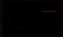
Regarding the FFT and filters: Not sure what you are referring to here. Could you explain further? Most FFT graphs I've seen online don't look nearly as "clean" as the one I linked. Does the filter have an affect on how the graph is displayed?
Regarding modeling AC transformers: I have one of those modeled in another schematic. I'll include that. I will be using a HV maida regulator for the power supply. As a placeholder I'll probably model a CLCRC PSU I've used in the past. That should be easier than modeling a HV regulator for now.
I didn't know about the power functionality. On Windows its Alt-click. Very handy.
I'm having an issue I'm hoping someone can help with. The amp is not built yet, but I have some EL33s I've been playing around with that all seem to have the same quirk. I have a bottlehead crack that's been modified to take 6J5s as input tubes. Up until now, I've been using 6J5 -> EL3N adapters to use EL3N tubes as drivers. It works very well.
Yesterday I connected G2 to anode to use EL33 tubes. For the EL33s, I can a hear a pretty prominent 120hz hum coming through both channels. This only happens with EL33s, but not my EL3Ns or 6J5s. Which is weird considering the EL3N and EL33 are essentially the same tube. I was wondering if someone could help diagnose why this might be happening with the EL33s.
Symptoms: 120hz hum. Only with EL33 tubes. Hum does not change with volume control. I doubt it's PSU ripple, as all my other tubes don't produce this hum.
What I've tried:
- EL33 has a metal shield connected to pin 1, but EL3N has the shield connected to the cathode. I tried removing pin 1 to ground, and connected pin 1 to cathode (Like EL3N).
- Flip-flopped tubes, and rotated in a 3rd EL33.
- G2 connected to anode with wire instead of 100 ohm resistor (the EL3N adapter does not use a resistor here, so I thought that difference might cause it, just to rule out differences in set up)
Any help would be appreciated. I'm stumped.
Regarding the FFT and filters: Not sure what you are referring to here. Could you explain further? Most FFT graphs I've seen online don't look nearly as "clean" as the one I linked. Does the filter have an affect on how the graph is displayed?
If you use the window function "Kaiser-Bessel" and a parameter of 20 - I was advised a while ago on this. If you've not seen windowing - think of it as a shape that modifies the value of a sample based on those around it (it gets used in optics deconvolution where I've bumped into it before).
Hey everyone, I ended up finishing this project a while back and forgot to update this thread... but it's done! The biggest problem and what took the longest was getting it quiet. Turns out, having the PT under the chassis close to the entire circuit is asking for all sorts of trouble, and was inducing a lot of hum. I knew that would happen, but I tend to make things difficult for myself.
But I'm super proud that I managed to get it completely silent! To get it silent, I had to experiment with different brands of toroid transformers, and found the antek transformer to have the least amount of stray fields. I also had to shield it with a steel cover, also from antek. Then I had to rotate it around to find the point where the magnetic fields leaked the least into the circuit. Overall it was pretty difficult, and I probably wouldn't build another amp this way. Power transformers belong on top of the chassis or in a separate chassis.
Some final specs:
Overall it sounds amazing. Definitely the best-sounding amplifier I have. Big thanks to everyone that helped me along the way on this thread. This was a massive learning project, and I'm excited to apply my new knowledge to other builds. Up next I will be experimenting with DHTs!


But I'm super proud that I managed to get it completely silent! To get it silent, I had to experiment with different brands of toroid transformers, and found the antek transformer to have the least amount of stray fields. I also had to shield it with a steel cover, also from antek. Then I had to rotate it around to find the point where the magnetic fields leaked the least into the circuit. Overall it was pretty difficult, and I probably wouldn't build another amp this way. Power transformers belong on top of the chassis or in a separate chassis.
Some final specs:
- Input tubes (single triode sockets): 6J5, EL33, 6C4 + many more (with adapter), and all equivalents
- Input tubes (dual triode): 6SN7, 6SL7, 12A/U/X7 (with adapter), and all equivalents
- Output tubes: EL33, EL34, EL38, KT66/77/88, 807 (with adapter), and all equivalents
- Input section: gyrator loaded, DC heated for minimum hum when using EL33 tubes, which tend to have bad heater-cathode leakage.
- Output section: 5K:8/16/32 output transformers, AC heated
- OPTs: Monolith magnetics amorphous core
- PT: Antek toroid under the chassis
- PSU: Maida-regulated with a high/low B+ switch
- B+: 250V or 370V depending on selection switch on the rear. 250V provides happy a operating point for EL33 and 6L6 (non-GC) output tubes, and 370V is for every other output tube. The 250V setting can also be used as an alternative operating point for EL34, KTxx, etc.
- Rear: RCA inputs, speaker taps, large heatsink for the maida regulator, impedance switch for 8/16/32 OPT secondaries.
Overall it sounds amazing. Definitely the best-sounding amplifier I have. Big thanks to everyone that helped me along the way on this thread. This was a massive learning project, and I'm excited to apply my new knowledge to other builds. Up next I will be experimenting with DHTs!

- Home
- Amplifiers
- Tubes / Valves
- First time amplifier design help, critique, and suggestions