Time for a filament cell
Using single alkaline cell, plus 8R2 to drop the excess volts at 50mA filament current, I test again.
This time, I have reliable and repeatable anode voltages.
Distortion is repeatable and around 0.5% until about 13V output, similarly to before.
Best performance appears to be with a quiescent current of 3.5 to 5mA. Gain varies between 7.7 and 8.2 V/V depending on the anode voltage (1/2 to 2/3 B+ span)
Using 200k LNFB from plate to grid, gain is roughly halved (not surprising being as the load is 100k), the improvement in THD is barely discernable. That is until input signal is increased sufficiently to produce output voltages about 20V, maybe a 1/3rd increase.
So, being as output seems to be fairly clean, to an almost respectable voltage, I disconnect the LNFB, and look for a transformer.
I havent even bothered to draw a load line at this point, so reflected impedance is a bit of a guess
I have a nice pair of headphones, HD650, 300R, but they really need something to drive them, and I have no headphone amp.
I start with a twin primary twin secondary PCB mount thing (115/115:6/6).
I have a DC blocking anode capacitor, 0.68uF, Mylar, so no need to worry about DC.
Primary wired as 115V and between anode capacitor, and ground, and the secondary wired as 12V.
Without testing and as a guess, 115/12, gives a rough ratio of 9.5:1, or Z ratio of about 92:1.
With the 300R Sennheiser, reflected Z is about 30k.
I've never even tried a parafeed transformer output, if this is what it is.
I have some doubts the capacitor is large enough, but I try anyway
I set a fixed input signal, and measure the output connected to a 330R load resistance connected to the secondary.
I can get to a volt or so, but it takes some drive to get there, this is only a single stage, so another stage maybe needed.
Since these headphones have a claimed 105dBSPL/V, 100dB/mW then 1-3V output might just be enough?
Wired as pentode though, and the gain may be enough...
Last edited:
2 stages
Now that I have got a reasonable result using a single stage, CCS anode load at 5mA, I consider another stage necessary to get enough gain to drive an OPT and real load.
I used 2 identical stages, biased at the same CCS current , with the grid on both stages at -2.1V as an initial test.
A single stage with these operating points, when triode wired, gives a gain of roughly 8 V/V, so cascading two of these stages should give a gain of about 64 V/V.
Taking a single FFT at near maximum output, 31V p-p, 11V RMS, requires drive voltage of 0.5V p-p, 180mV RMS.
Gain about 62 V/V. THD roughly doubled to 0.7%.
A bonus, now the THD is dominated by 2nd, rather than 3rd 🙂
This is still Open Loop, and I have quite a bit of gain in hand, the output of 31V p-p is about 1/3rd B+ and this output may just be enough, coupled to a 10:1 OPT.
If I need more voltage swing, then the B+ will need to go up to 120V or more.
I need to sit down and consider biasing changes to optimise input and output stages, rather than bias them the same.
Perhaps, some FB from output to input cathode, or LNFB in the output stage, to hopefully linearise it slightly.
Schematic coming once I get some time to sketch it out.
Last edited:
Tangent - trying a 1J24B in triode - just for kicks.
I only had about 15 minutes spare time today, while eating lunch!
So using 1J24B and increasing the CCS emitter resistor from 220R to 1k2, to reduce Iq from 4.5mA to about 1mA, I tested gain quickly.
I found that with both CCS circuits fed from the same B+, suddenly I could not bias each stage appropriately, where with two 1J29B biased in the same fashion, I thought I could.
Using independent filament power for each valve solved the issue though.
I think I have a missing ground return somewhere, but no more time to investigate, for today
I get about 10 V/V, but found I needed to reduce Iq further, to about 0.8mA, for anode volts to settle at 60V (B+ 90V).
THD performance at the limit of clean output, is pretty much the same.
Finally, a schematic for those interested - it's still a WIP so improvements are definitely possible!
At B+ 90V, in this design, I measured about 1% THD at max output (2V p-p) at around 15mW, which should be OK with 300R cans like sennheiser HD600 etc.
At B+ 90V, in this design, I measured about 1% THD at max output (2V p-p) at around 15mW, which should be OK with 300R cans like sennheiser HD600 etc.
Attachments
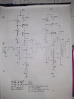
The realisation Dawns on me that I have not explained any of the development in the circuit.
My earlier posts referred to open loop, no local NFB. I added local feedback to the output stage only at first, aiming for a gain of 4 or 5 V/V. Then I ended up doing the same thing to the input stage, only less feedback.
The circuit in the post above achieves about 15-18mW using the obsolete RS 115+115:15+15 30VA toroid, THD better than 1% with 300R load.
In testing I couldn't find a EI core transformer that wasn't far more lossy overall, and severely bandwidth limited.
Using another toroid, same RS type, but with dual 20V Secondaries yielded more output but at elevated levels of THD.
It may turn out that this toroid works better if the B+ voltage is raised from 90V to 120V, for example.