any bright yellow ? 😛
I think we can also do in blue and white, for yellow I have to ask. Good idea! 😎
Lc, when do you expect to have chassis prices and pictures ready? And what are the currently recommended power supplies?
I have to press hard on this guy who makes chassis, it seems he forgot what he promised me. Next days will be more intense for this project from my side surely, so expect more action here.

Great to see that you finally posted some measurements, although not sure what exactly they represent, since we cant see where the cables of the scope are connected.
any chance to show the ripple value on 20mV scale not 20V ? measuring the ripple on 20V scale is like measuring the hair thickness with a ruler.
like here http://www.diyaudio.com/forums/vend...ne-mosfet-amplifier-module-8.html#post3882773 for example
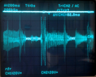
I noticed that in almost all the measurements posted the ripple was measured on same scale, 20V, and in some places audio signal on 2V scale. what's the point of showing these pictures if they are measured on the wrong way. I doubt that you don't know how to use a scope. unless you want to hide the real value of the ripple, why not post the measurements like me and LC did, on 20mV 50mV and 100mV scale. not to mention that SMPS2000R which was tested was not tested in ideal conditions and without any filters as your SMPS has already on board. because we want to show what the SMPS can do not how good are the filters. we are not trying to sell filters, but SMPS, right ?
In the last picture shown, the ripple is about 4.5-5Vpp. most of the oscilloscopes are very non-linear when measuring low amplitude signals on a high input voltage scale. We can exploit this issue and show near perfect waveforms. If we measure 0.5V or less on 20V scale we will see nothing, or unchanged values. if we measure 3V on 20V scale will read about 2.5V because low signals are more attenuated due to probes, input filters and anti-aliasing filters for digital oscilloscopes. some cheap oscilloscopes have have high noise floor and low-amplitude signals are not visible.
any chance to show the ripple value on 20mV scale not 20V ? measuring the ripple on 20V scale is like measuring the hair thickness with a ruler.
like here http://www.diyaudio.com/forums/vend...ne-mosfet-amplifier-module-8.html#post3882773 for example
I noticed that in almost all the measurements posted the ripple was measured on same scale, 20V, and in some places audio signal on 2V scale. what's the point of showing these pictures if they are measured on the wrong way. I doubt that you don't know how to use a scope. unless you want to hide the real value of the ripple, why not post the measurements like me and LC did, on 20mV 50mV and 100mV scale. not to mention that SMPS2000R which was tested was not tested in ideal conditions and without any filters as your SMPS has already on board. because we want to show what the SMPS can do not how good are the filters. we are not trying to sell filters, but SMPS, right ?
In the last picture shown, the ripple is about 4.5-5Vpp. most of the oscilloscopes are very non-linear when measuring low amplitude signals on a high input voltage scale. We can exploit this issue and show near perfect waveforms. If we measure 0.5V or less on 20V scale we will see nothing, or unchanged values. if we measure 3V on 20V scale will read about 2.5V because low signals are more attenuated due to probes, input filters and anti-aliasing filters for digital oscilloscopes. some cheap oscilloscopes have have high noise floor and low-amplitude signals are not visible.
Last edited:
To both AP2 and Cristi.
As i said previously, measurements are just accurate enough to eliminate an obvious bad designed SMPS. No need to fight on this, on my point of view. And, anyway, a comparative measure done the same way by the same equipment (as L.C will provide) will be the only fair judge.
About Ripples, we are in a special case, with the First One. It is a current feedback amplifier, and, as it, have lower ripple rejection at low frequency than a conventional LTP voltage feedback amplifier. And a better one at high frequencies. So, the results on this amplifier will be different than with an other, more conventional.
At low frequencies, as long ripple will not add audible noise, we don't care. At high frequencies, a look at harmonic distortion will tell if any major difference.
But the most important thing is the way SMPSs will behave in presence of the complex transients of a musical signal. How much instant amps they are able to deliver, how fast they regulate/recover. And this will be noticed by a different landscape in the listening sessions. The only interesting thing on my point of view.
Purely subjective, only applied to this special amplifier, and witch will not tell a lot about the SMPS itself, as one, less good on this amp, can be better on an other one. Unless one of them is a pure failure ;-)
On my side, i'm very interested to see if any general conclusion can be brought between regulated VS unregulated SMPS, in favor of one more than an other.
So, AP2 and Cristi, just be patient, wait silent for the results, it will be time at this moment, to add some tips (like Cristi did for the 0A measurements), to make the measurements more fair.
About static measurements, i suggest the real amp load to be plugged-in in // with the resistive charge. And, apart from rail voltages, to look at a a little amp out signal to see how it behave with the low z resistive charge in and out.
And thanks to you both for this unique occasion for us to compare your babies and, may-be, for you to improve some details on your.
Last edited:
If the dc output is completely clean , and you think that it is the filter, then add it on your smps .Great to see that you finally posted some measurements, although not sure what exactly they represent, since we cant see where the cables of the scope are connected.
any chance to show the ripple value on 20mV scale not 20V ? measuring the ripple on 20V scale is like measuring the hair thickness with a ruler.
like here http://www.diyaudio.com/forums/vend...ne-mosfet-amplifier-module-8.html#post3882773 for example
I noticed that in almost all the measurements posted the ripple was measured on same scale, 20V, and in some places audio signal on 2V scale. what's the point of showing these pictures if they are measured on the wrong way. I doubt that you don't know how to use a scope. unless you want to hide the real value of the ripple, why not post the measurements like me and LC did, on 20mV 50mV and 100mV scale. not to mention that SMPS2000R which was tested was not tested in ideal conditions and without any filters as your SMPS has already on board. because we want to show what the SMPS can do not how good are the filters. we are not trying to sell filters, but SMPS, right ?
In the last picture shown, the ripple is about 4.5-5Vpp. most of the oscilloscopes are very non-linear when measuring low amplitude signals on a high input voltage scale. We can exploit this issue and show near perfect waveforms. If we measure 0.5V or less on 20V scale we will see nothing, or unchanged values. if we measure 3V on 20V scale will read about 2.5V because low signals are more attenuated due to probes, input filters and anti-aliasing filters for digital oscilloscopes. some cheap oscilloscopes have have high noise floor and low-amplitude signals are not visible.
I did not put measures regarding the ripple .
2V/Div just my dummy load has a buffered output 10:1 (some photos show it)
Last photo today , use the probe on VCC rail , and probe on loudspeaker B & W 802 II , just you see (in practice ) how it behaves with 2.7 R reactive load .
Drop under voltage burst is measured only in one direction (not vpp ) . in this case you can see the reaction time in Both, including reset time ( for the amplifier that is important, not find a side unbalanced .
If you look better, "the error amplifier action" , in the DPS -500 follows the current demand with the same frequency as the current demand . can do this perfectly up to 300kHz signal at the input of the amp.
everything is easier , if you accept that the DPS - 500 is designed for amplifiers and includes a technology not usual .
If I can help you, I do not participate in GB. I have interest in LC , confirms only two of my misures .
1-The FFT at the output of amplifier ( 4R )
2-The behavior of the rail , with all the signs he wants.
You assume and deduce 😛
thanks anyway, for some explanations.
I hope my last measurement on the VCC rail, and on loudspeaker, with music, it is clear that the transient over 40Vp have current between 19 and 23Amp.
Sorry for my doubts 😀
Sorry for my doubts 😀
Is this "measurement" referring to post444?I hope my last measurement on the VCC rail, and on loudspeaker, with music, it is clear that the transient over 40Vp have current between 19 and 23Amp................
If not, then where?
Is this "measurement" referring to post444?
If not, then where?
Hi,
Yes, right out of the method but...this is when we listen. 🙂
Audio Transient are..audio transient.
I specified the song, anyone can verify in simple way.
Last edited:
Could you describe the "method" and the equipment so that we can replicate the results?
Did you use a 4ohms, or 8ohms speaker?
Was the PSU powering one channel?
Is the 40Vpk measured at the speaker terminals or somewhere else?
etc .....
I understand transients.
Did you use a 4ohms, or 8ohms speaker?
Was the PSU powering one channel?
Is the 40Vpk measured at the speaker terminals or somewhere else?
etc .....
I understand transients.
Could you describe the "method" and the equipment so that we can replicate the results?
Did you use a 4ohms, or 8ohms speaker?
Was the PSU powering one channel?
Is the 40Vpk measured at the speaker terminals or somewhere else?
etc .....
I understand transients.
Hi,
I think the setup is very simple.
CD player->amp->Loudspeaker (set mono input)
In my case, CD Player sony very old, Amplifier HB-300 mono (two mosfet for rail) one DPS-500-DA-GB version at +/-61V.
Speaker B&W 802 II, well known as a heavy load.
Oscilloscope: ch1 on vcc rail on amp.
" " ch2 on output (amp terminals output) (we measure as the amp see global load,incluse cable from amp to speaker)
Set your volume at the max possible (near to clip).
This measurement can give an accurate idea of the real load. the psu has to provide the current as transient sound (has nothing to do, test the psu with resistance as continuos current, this is good for smps for motors or lamps).
This measure + fft, we have a complete info on psu for audio, no other need.
Later I show same measure but with current Vs. speaker, maybe some not imagine well how many amperes pass with high speed.
Last edited:
Current feedback amps can deliver 500 or 1000V/µs.maybe some not imagine well how many amperes pass with high speed.
Yes, we have an idea of the instant currents involved 🙂
That's exactly the reason why we are interested in this SMPS contest.
Current feedback amps can deliver 500 or 1000V/µs.
Yes, we have an idea of the instant currents involved 🙂
That's exactly the reason why we are interested in this SMPS contest.
No doubt on speed of response amp . but we need to see , what is the load, becouse reactive , very different from static resistive .
also, or we play in abbondance of capacitors , or we play at high speed. in the case of smps , we need to get clean also. these are two things that are absolutely to be solved serious, without business contamination. 🙂
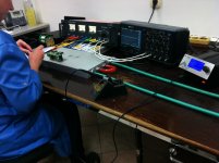
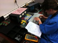
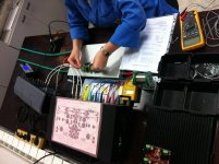
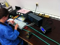
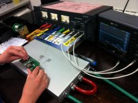
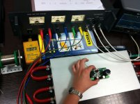
Calibrating and testing the First One
As clearly seen on last pic a liquid cooled Al-block heatsink is on constant 23°C temperature so all First One modules are calibrated at the same conditions. Scope is present just to monitor that all output signals are in order.
As clearly seen on last pic a liquid cooled Al-block heatsink is on constant 23°C temperature so all First One modules are calibrated at the same conditions. Scope is present just to monitor that all output signals are in order.
Attachments
I am in awe, by the hole operation bringing us "the first one", your testfacility and also by your extremely clean desk.... I do try but always end up in chaos...🙂
I am so looking forward to the results from you and future users, I am not (yet) on the list but that's a matter of time...
Keep up the very good work!
I am so looking forward to the results from you and future users, I am not (yet) on the list but that's a matter of time...
Keep up the very good work!

Hi LC,
I would advise to use an ESD wrist strap during testing.
Regards,
John
The woman in the picture is wearing ESD protective robe.
Regards,
Ales
- Home
- Vendor's Bazaar
- First One - mosFET amplifier module