Some more pics for those interested in Black Mamba chassis. WYSIWYG 😉
Where did you get those fantastic looking speaker binding posts!?
FO S soon after L 😉LC just has to work on the "S" version for those of us with sensitive speakers
😀
Best,
Anand
What about you? 😀My friend want both the 2 channel and the 4 channel as well.
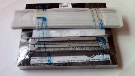
These are fine copies of Furutech, named Acrolink 😉Where did you get those fantastic looking speaker binding posts!?
you can get them here for 1/3 of that price
Audio Catalog i used to build wires for dummys at head-fi so they are legit and take paypal.
Audio Catalog i used to build wires for dummys at head-fi so they are legit and take paypal.
you can get them here for 1/3 of that price
Audio Catalog i used to build wires for dummys at head-fi so they are legit and take paypal.
Not everything is like it looks like.
Allen's Illustrated building Journey
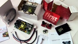
As promised, here are the photos of my First One build.
I am not an expert amp builder. This is in fact my second amp build. So I think this illustrated photo journey will encourage even the beginning builder to build this incredibly worthwhile Amp. This could very well be the last amp You will need to build! (I will be building more as I have a multi-amp system 😀)
The parts I used are not too exotic and readily available. I would say this is a "medium" cost build. As others have mentioned in this thread, it is worthwhile getting premium parts for this amp, cost permitting. At the same time, one can be more resourceful with the chassis also. I would have loved to find a fried McIntosh power amp with the blue VU meters on the front for this project, but the availability was not happening at the time.
I used the 2U chassis from the DIYaudio shop. The binding posts are Dayton Audio BPP-G Premium (# 091-620) and the RCA jacks are Part's Express chassis mount (# 091-1120), both from Parts Express. The power switch is Arcolectric DPST 15 Amp 250 volt (# 1091-1061-ND) from Dig-Key.
As promised, here are the photos of my First One build.
I am not an expert amp builder. This is in fact my second amp build. So I think this illustrated photo journey will encourage even the beginning builder to build this incredibly worthwhile Amp. This could very well be the last amp You will need to build!
(I will be building more as I have a multi-amp system 😀)The parts I used are not too exotic and readily available. I would say this is a "medium" cost build. As others have mentioned in this thread, it is worthwhile getting premium parts for this amp, cost permitting. At the same time, one can be more resourceful with the chassis also. I would have loved to find a fried McIntosh power amp with the blue VU meters on the front for this project, but the availability was not happening at the time.
I used the 2U chassis from the DIYaudio shop. The binding posts are Dayton Audio BPP-G Premium (# 091-620) and the RCA jacks are Part's Express chassis mount (# 091-1120), both from Parts Express. The power switch is Arcolectric DPST 15 Amp 250 volt (# 1091-1061-ND) from Dig-Key.
Attachments
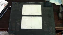
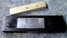
Chassis Cutouts: bottom
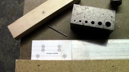
I have a pretty modest shop, mainly for wood. No drill presses, CNC's or bandsaw. I used a Milwaukee Magnum hand drill, jigsaw, metal files, several punches, clamps, a basic drilling jig and many custom jigs. I would say a good drill and the drilling jig are essential. The Big Gator Tools STD1000DGNP V-Drill Guide is very nice, and on my list for future builds. 😉
I printed out the drilling templates provided with the instructions of the various modules. Be sure to double check your scaling, as 100% is NOT the right size on some of the printouts. I am sorry I do not remember which ones 😱
In the case of the bottom plate and back plate, I did not use a drilling jig, but I did punch the holes first. I also reamed the burrs out on both sides using a larger bit. There are better ways to do this, but this is what I had at the time. A light touch is what is needed, to prevent the drill "grabbing".
For the switch cutout, I drilled several holes and used a jigsaw to square it out. I filed the burrs. Aluminum cuts very nice, and I really enjoyed working with it.
After I had the SMPS mounted and the switch installed, I realized I forgot the Grounding (Earth) bolt hole, so I thoroughly cleaned my work area to complete that hole (did not want to get shards on the circuits 😱).
You may find that some of these processes I have done, You may not want to do! 😱
Attachments
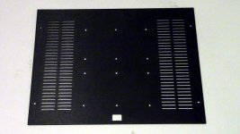
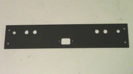
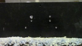
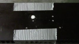
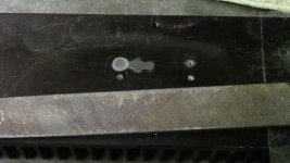
Back Plate Cutouts:
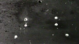
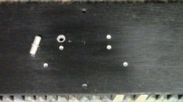
I created my own paper template for the back. The drilling process was similar to the bottom plate. The Dayton Audio binding posts had a "key" to hold it in place, while screwing down the bolt. I used the jigsaw to cut the slot. You noticed I angled each side so when using bare speaker wire, the speaker wire would "settle" towards the side of the room the speaker is on.
Initially, I was not too happy with how close the DC sense board mounted to the chassis, using the supplied binding post hardware. My local hardware store did not have additional nuts for the threads on these posts, so I found the plastic spacers You see in the last photo. This turned out to be a very successful and affordable alternative.
Attachments
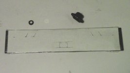
Heatsinks
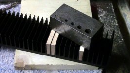
For mounting the FO modules to the heatsinks, I planned on using 4-40 screws. This required using a #43 (2.2606mm or 089") drill bit to pilot the hole for the 4-40 tap. I bought new bits and taps for this project.
Like on the outer plates, I used a paper template to mark the hole locations. I took this a step further and made a hole guide jig with 3/16 aluminum plate. I wanted to make sure I had the holes right first on this hole jig first, and I wanted to make it easier to find the hole locations via the jig, so it would be easier to clamp the drilling jig. Clear as mud right! This is when it is essential to have a clamped drilling jig. The problem in general, is there are no drilling jigs available in this small of a size. If You want a million dollar idea, this might be it. In this case, I had to create a custom jig, and it had to be true and straight. Luckily, I found a plastic insert that had a 4-40 diameter hole, and it was a 1/4" diameter on the outside. So I used my basic drilling jig to drill a 1/4" hole about 3/8" into a 3/4" piece of hard wood (maple). I inserted the plastic insert and drilled the remainder of the hole all the way thru with the #43 bit. I really hope this makes sense. 😱
I found a similar plastic insert to make a similar jig for the tap also. I needed a thinner jig for the tap, as my basic drilling jig was too thick.
After a lot of fidgeting, nudging and double checking, I was able to get all the holes drilled and the majority of them tapped.
Attachments

Last edited:
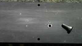
You may remember what happened next...
Everything was going well, I had all the holes tapped with the plug tap, now all I needed to do, was finish all the holes with the bottom tap. I got all of them done. I was down to the last hole, and SNAP! - the tap broke, in the hole!
I was really glad for this community, because You All helped me get thru this. This is actually the first time I have tapped Anything, so I certainly did not have the techinque down. 😱 Looking back at the experience, I should have been backing out and taking smaller bites then I did. I could not blame it on cheap taps, becuase I got Hanson Carbon taps, and those are supposed to be good ones.
There are a lot of different ways to get a tap out. Do not bother trying to drill it out, it is way too hard. I tried breaking it out, but this size is so small, that I ended up just making a bigger mess. What I ended up doing, was driling the hole bigger on both sides of the heat sink, and pushing the tap thru the hole. I was lucky I was in between the fins! You might want to bear that in mind when lining up your holes, go in between the fins. 🙂
Attachments
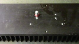
So now we have a BIG hole...
So what to fill the hole with, I had a few ideas. But I did not want to be a dollar dumb and penny wise, so I followed the advice given to me from all You DIYaudio members. 😎 I went with aluminum rod glued in with Loctite thread compound. I heated the heat sink in the oven and froze the rod. It only took a moderate amount of pounding to get the pin in. I was lucky I had a worn 1/4" drill bit that was a bit under 1/4" and the rod was a hare larger then 1/4" also.
So what to fill the hole with, I had a few ideas. But I did not want to be a dollar dumb and penny wise, so I followed the advice given to me from all You DIYaudio members. 😎 I went with aluminum rod glued in with Loctite thread compound. I heated the heat sink in the oven and froze the rod. It only took a moderate amount of pounding to get the pin in. I was lucky I had a worn 1/4" drill bit that was a bit under 1/4" and the rod was a hare larger then 1/4" also.
Attachments
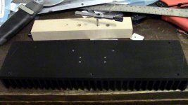
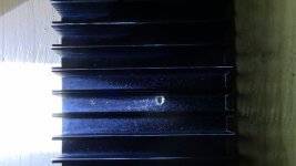
More on getting that hole straight
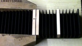
Getting the new hole straight took a bit of jigging. I wanted to drill from the fin side of the Heatsink as I wanted to keep the hole between the fins, keeping the fins in tack. I created wood trapezoid shapes to fit right between the fins. These turned out to be very handy jigs, as I made them a tiny bit higher then the fins themselves, so even when doing work on the flat side, the heatsink could rest firmly on any surface without deforming the fins.
Once I had a straight hole between the fins and thru the base, I could enlarge it to any size I needed from the flat side. As mentioned above, that size ended up being a bit smaller then 1/4"
Attachments

Last edited:
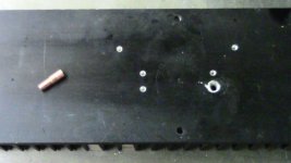
Getting things clean and smooth again
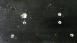
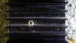
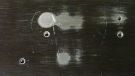
So now the hole is filled, but we have some pin sticking out and some excess loctite to deal with. Cleaning the loctite is not an issue if You get to it right away. I did on the flat side, but I forgot it would leak some on the fins. I did not get to that in time, and even after a couple of hours of trying low heat flame, solvents, fine steel wool, and plastic picks, I was not completely successful getting it all off. I did not want to use high heat, as that could break down the loctite bond on the pin. So, even as I write this, First One is cooking nice and warm with some loctite residue on that heat sink. 😱
I used a fine toothed hand saw to cut the pin down close to the surface. I used duct tape as a protective coating for the surface. I then proceeded with a coarse file, a fine file, 600 sand paper, 1200 sand paper, and finally 2000 sand paper. For filing, I used clear packing tape as a protective measure. Once to sanding, I did not feel the tape was necessary.
As you can see from the photos, I was not completely successful in getting this surface back to its "new" state. The tap removal process left it with some battle scars that would require a significant amount of sanding to remove. I did not have the tooling for that, and although not perfect, I do believe from the performance of the amp, that this heatsink is doing the job.
Attachments
Artsy,
I would think some CA debonder would probably remove the residue from the loctite. You can usually find this at a good model shop. Some that I have used was made of Nitro-methane but I think there are other debonders besides that.
ps CA= Cyano acrylate
I would think some CA debonder would probably remove the residue from the loctite. You can usually find this at a good model shop. Some that I have used was made of Nitro-methane but I think there are other debonders besides that.
ps CA= Cyano acrylate
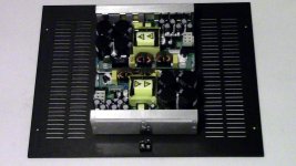
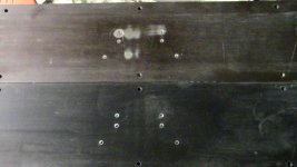
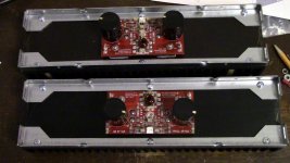
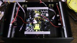
Yay! Mounting the Modules!
It was a very happy night when I finally mounted the modules! I was starting to feel hope again!
I used Aavid Thermalloy Aluminum Oxide Ceramic themo pads for the Mosfets. These were 2.03 mm thick, so that left a gap between the driver chips and the heatsink to fill. The closest thing I could locally get, was a 1"wide by 1/16" (1.5875) thick aluminum strip. I used my aluminum plate hole jig to drill the holes in this strip. I was not sure if this being about 0.44 thinner was going to be a problem or not. I dry mounted the modules to make sure, and I am happy to report that the drivers did indeed adapt and mount flat.
Looking at the the mounted modules with the chassis brackets installed, one would have no idea of the battle I went thru to get this project to this stage.
Attachments

Power Wiring:
Power Wiring was pretty straight forward. Most of the wiring needed came with the Hypex SMPS. I used 14 gauge stranded copper 3-wire from a spliced outdoor extension cord I had, for the mains wiring to the switch. Black and White to the switch and Green to the chassis Earth bolt.
I used "Fast-On" connectors for all the power connections. I had some insulated ones for the module DC connections. I bought bare bass ones for the switch and speaker connections. I used heat-shrink wrap to insulate these bare brass connectors.
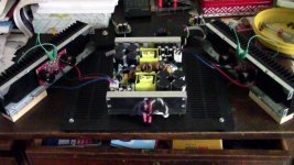
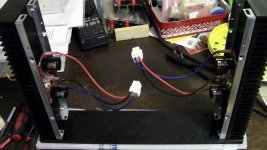
With all the DC connected, I could now test and calibrate the modules. Two mistakes I made the first time around calibrating this unit:
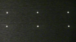
The first one, I mentioned earlier in the thread, is that the first test set-up I had, I had the heatsinks laying on their fins. The system runs pretty hot like that, and there is no way to trim the numbers down to their desired levels. 😱 I did not want to deal with the tight spacing with the chassis sides completely assembled, so I went with the set-up in the photo below, which worked well.
The second mistake is not giving the modules enough time to adjust to the new settings. What I did not understand at first, is the numbers are going to fluctuate, the goal is to get the "range" of fluctuation to DC off-set of 0 and a Bias of 180 mV. I needed two DMMs and I needed to watch them when I was getting close.
As other members have suggested, writing the adjustments down helps a lot also. 😀
I posted my measurements earlier in this thread, and they are a little misleading (as I did not wait long enough to get the full range of fluctuations).
The DC off-set is between 1.5 mV to -1.5 mV
and the Bias is between 178 - 190.
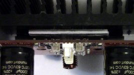
The other mistake I made, is I soldered the DC sense ribbon wires on the outside (Cap side) of the boards. I do not think this would affect the performance, but I did not like how it looked and how close the ribbons would be to the speaker wires. So I un-soldered them, and re-soldered them to the back of the boards.
Power Wiring was pretty straight forward. Most of the wiring needed came with the Hypex SMPS. I used 14 gauge stranded copper 3-wire from a spliced outdoor extension cord I had, for the mains wiring to the switch. Black and White to the switch and Green to the chassis Earth bolt.
I used "Fast-On" connectors for all the power connections. I had some insulated ones for the module DC connections. I bought bare bass ones for the switch and speaker connections. I used heat-shrink wrap to insulate these bare brass connectors.
With all the DC connected, I could now test and calibrate the modules. Two mistakes I made the first time around calibrating this unit:
The first one, I mentioned earlier in the thread, is that the first test set-up I had, I had the heatsinks laying on their fins. The system runs pretty hot like that, and there is no way to trim the numbers down to their desired levels. 😱 I did not want to deal with the tight spacing with the chassis sides completely assembled, so I went with the set-up in the photo below, which worked well.
The second mistake is not giving the modules enough time to adjust to the new settings. What I did not understand at first, is the numbers are going to fluctuate, the goal is to get the "range" of fluctuation to DC off-set of 0 and a Bias of 180 mV. I needed two DMMs and I needed to watch them when I was getting close.
As other members have suggested, writing the adjustments down helps a lot also. 😀
I posted my measurements earlier in this thread, and they are a little misleading (as I did not wait long enough to get the full range of fluctuations).
The DC off-set is between 1.5 mV to -1.5 mV
and the Bias is between 178 - 190.
The other mistake I made, is I soldered the DC sense ribbon wires on the outside (Cap side) of the boards. I do not think this would affect the performance, but I did not like how it looked and how close the ribbons would be to the speaker wires. So I un-soldered them, and re-soldered them to the back of the boards.
Attachments

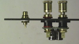
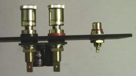
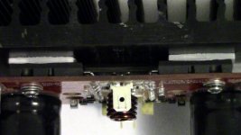
Signal and Speaker wiring:
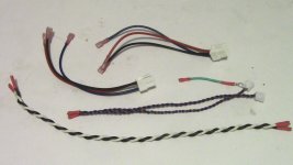
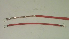
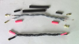
For speaker wiring, I used 8 strands of 24 gauge solid core copper for each conductor. The wire itself is CAT6 networking wire. I normally use 4 strands of this (CAT5) for each conductor for my speaker wires, but due to the higher current output of this amp, I wanted to over kill a little. These wires are terminated with the brass "Fast-on" connectors on each side, so that allows me to try other wire arrangements down the road. This sounds pretty good to me as is today, so we will see...
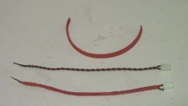
For the signal wiring, I used 22 gauge solid core copper for each conductor. I normally use a single strand of 24 gauge for this, but Lazy recommended shielded 75 ohm coaxial cable, which has 22 gauge conductors. Again, I wanted the wire to be sized correctly for this amp. I personally do not like the signal ground to be the shield, which is why I did not use coaxial cable, and instead created my own shielded cable. I do not have any scientific reasoning for this, just a gut instinct.
As shown in the photos, I heat-shrinked the twisted pair carrying the signal. I then covered this with copper foil tape. The copper foil tape came out of my stained glass studio. It is available at any stained glass supply store. (I order from Glass Crafters). I then solder on a 22 gauge bare copper lead on one side of the shield. This copper lead then gets soldered to the outer ring of the RCA socket along with the signal ground. I then covered the shield with another layer of heat-shrink. This seems to work good, as is this is the quietest amp I have had the pleasure of owning!
Thankfully, I was able to figure out the Molex connectors for these signal wires, in case I want to try other kinds. If you recall, I broke six connectors, one right after another. I thought I needed a customized tool. As it turns out, the brass pins came on a reel of tabs. I figured you where supposed to cut the tabs in the middle and fold the tabs around the pin and slide them in the connector. Maybe that is what the machine does to these pins on the assembly line, but it was not working for me. Instead, I cut the tabs off completely, and inserted the pin straight in. I was concerned there would not be enough resistance for the backs to lock, but they did, and very snug and secure. I was glad I could find the two that flew across my studio. That was a miracle!
For speaker wiring, I used 8 strands of 24 gauge solid core copper for each conductor. The wire itself is CAT6 networking wire. I normally use 4 strands of this (CAT5) for each conductor for my speaker wires, but due to the higher current output of this amp, I wanted to over kill a little. These wires are terminated with the brass "Fast-on" connectors on each side, so that allows me to try other wire arrangements down the road. This sounds pretty good to me as is today, so we will see...
For the signal wiring, I used 22 gauge solid core copper for each conductor. I normally use a single strand of 24 gauge for this, but Lazy recommended shielded 75 ohm coaxial cable, which has 22 gauge conductors. Again, I wanted the wire to be sized correctly for this amp. I personally do not like the signal ground to be the shield, which is why I did not use coaxial cable, and instead created my own shielded cable. I do not have any scientific reasoning for this, just a gut instinct.
As shown in the photos, I heat-shrinked the twisted pair carrying the signal. I then covered this with copper foil tape. The copper foil tape came out of my stained glass studio. It is available at any stained glass supply store. (I order from Glass Crafters). I then solder on a 22 gauge bare copper lead on one side of the shield. This copper lead then gets soldered to the outer ring of the RCA socket along with the signal ground. I then covered the shield with another layer of heat-shrink. This seems to work good, as is this is the quietest amp I have had the pleasure of owning!
Thankfully, I was able to figure out the Molex connectors for these signal wires, in case I want to try other kinds. If you recall, I broke six connectors, one right after another. I thought I needed a customized tool. As it turns out, the brass pins came on a reel of tabs. I figured you where supposed to cut the tabs in the middle and fold the tabs around the pin and slide them in the connector. Maybe that is what the machine does to these pins on the assembly line, but it was not working for me. Instead, I cut the tabs off completely, and inserted the pin straight in. I was concerned there would not be enough resistance for the backs to lock, but they did, and very snug and secure. I was glad I could find the two that flew across my studio. That was a miracle!
Attachments

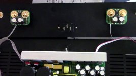
Chassis assembly:
Finally, all the parts are fabricated, it was getting pretty exciting!
What I do not realize, is that I would not be able to get the front plate of the chassis on, without taking the chassis completely apart again. I did not have a screw driver small enough or thin enough to fit between the modules and smug up in the corners at a reasonable angle to crank down on the screws. Glad I was able to keep everything modular on this build.
Once the front was centered and secure, the rest of the chassis assembly was pretty straight forward.
I made both my speaker wires and signal wires a bit long, but again, that does not seem to affect the performance of the amp.
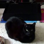
I laughed when I took the last photo, as that is the typical view we have seen thru out this thread. But what I really like about this "typical" photo, is that it is in my living room, hooked up to my system. 😀
Finally, all the parts are fabricated, it was getting pretty exciting!
What I do not realize, is that I would not be able to get the front plate of the chassis on, without taking the chassis completely apart again. I did not have a screw driver small enough or thin enough to fit between the modules and smug up in the corners at a reasonable angle to crank down on the screws. Glad I was able to keep everything modular on this build.
Once the front was centered and secure, the rest of the chassis assembly was pretty straight forward.
I made both my speaker wires and signal wires a bit long, but again, that does not seem to affect the performance of the amp.
I laughed when I took the last photo, as that is the typical view we have seen thru out this thread. But what I really like about this "typical" photo, is that it is in my living room, hooked up to my system. 😀
Attachments


So that brings us to the completed product, making music and movies come alive in my living room.
This took seven weekends to put together. Two weekends were spent on the tap "incident". Bare in mind, amp building is not my main line of work, there was a lot of learning curve thru out this build. Having said that, that means anyone can assemble this amp. 🙂
This took seven weekends to put together. Two weekends were spent on the tap "incident". Bare in mind, amp building is not my main line of work, there was a lot of learning curve thru out this build. Having said that, that means anyone can assemble this amp. 🙂
Attachments
Latest impressions
You got that right! My Realtek DAC does not stand a chance against the M-Audio. I "tolerated" Realtek, because it is eight channel. The M-Audio has four, which actually would be just enough to squeak by had one channel not blown when my Lightspeed volume control blew. I do not know what caused that, I just remember a huge static charge went from my finger up the signal interconnect and that was it. We get really bad static electricity in the winter here, and that Lightspeed did not like it. Anyway, back to DACs. With my LM3875s, I could "live with" the shrill and grain of the Realtek audio. But with the First One, it sounds so noisy and edgy, that I would prefer to have 2.1 channels of smoother, blacker background sound, then 4.2 channels of surround sound.
Needless to say, despite the fact, that I would really like to build my next set of Arrays, the DAC really is the next step. The massive hang up for me is getting multi-channel. Odd, really, considering all the advancements in surround sound, DSP, FIR processing and digital multi-way speaker systems. I understand that DACs can be stacked, but there needs to be an interface that runs that multi-channel signal to the stack of DACs, and the interface needs to keep that stack of DACs in sync with each other. That is the "missing link", and a topic for another thread. 😉
Getting back to the First One...
I need to explore the following observation more, but one thing I have noticed in the past, is when I set up a given speaker system in my room for a relatively flat listening seat response, I found that the highs flattened the sound stage. So I have always preferred a slow, gradual high roll-off, starting at about 1.5 kHz. But, yesterday I came across that convolution and "accidentally" tried it on my arrays. The result was a smooth airy extension of the highs while still maintaining a wide soundstage. I would say the soundstage was even enhanced, because it did extend into the highs, which I have not heard before. In fact the highs are so smoothly resolved with the First One. I have to wonder what a ribbon tweeter would sound like thru this amp. I will know soon enough, as I have one on an old open baffle system I am restoring for my brother. It was my first speaker creation. It is all in pieces at the moment, but it will get its chance with First One also. It is nice that I can enjoy highs instead of seeing them as a limiting factor to a wide and deep soundstage. Like I say, I am reserving my excitement a little on this, because I want to dig deeper on what is going on here. 😉
I hope You all enjoy the photos,
Allen
Differentiating among system's components, cabling, etc. was never simpler than this.
You got that right! My Realtek DAC does not stand a chance against the M-Audio. I "tolerated" Realtek, because it is eight channel. The M-Audio has four, which actually would be just enough to squeak by had one channel not blown when my Lightspeed volume control blew. I do not know what caused that, I just remember a huge static charge went from my finger up the signal interconnect and that was it. We get really bad static electricity in the winter here, and that Lightspeed did not like it. Anyway, back to DACs. With my LM3875s, I could "live with" the shrill and grain of the Realtek audio. But with the First One, it sounds so noisy and edgy, that I would prefer to have 2.1 channels of smoother, blacker background sound, then 4.2 channels of surround sound.
Probably not, drop a question to MSB. Analog DAC can drive two channels so it would need to stack them to fill all the channels you need.
Needless to say, despite the fact, that I would really like to build my next set of Arrays, the DAC really is the next step. The massive hang up for me is getting multi-channel. Odd, really, considering all the advancements in surround sound, DSP, FIR processing and digital multi-way speaker systems. I understand that DACs can be stacked, but there needs to be an interface that runs that multi-channel signal to the stack of DACs, and the interface needs to keep that stack of DACs in sync with each other. That is the "missing link", and a topic for another thread. 😉
Getting back to the First One...
I need to explore the following observation more, but one thing I have noticed in the past, is when I set up a given speaker system in my room for a relatively flat listening seat response, I found that the highs flattened the sound stage. So I have always preferred a slow, gradual high roll-off, starting at about 1.5 kHz. But, yesterday I came across that convolution and "accidentally" tried it on my arrays. The result was a smooth airy extension of the highs while still maintaining a wide soundstage. I would say the soundstage was even enhanced, because it did extend into the highs, which I have not heard before. In fact the highs are so smoothly resolved with the First One. I have to wonder what a ribbon tweeter would sound like thru this amp. I will know soon enough, as I have one on an old open baffle system I am restoring for my brother. It was my first speaker creation. It is all in pieces at the moment, but it will get its chance with First One also. It is nice that I can enjoy highs instead of seeing them as a limiting factor to a wide and deep soundstage. Like I say, I am reserving my excitement a little on this, because I want to dig deeper on what is going on here. 😉
I hope You all enjoy the photos,
Allen
For the signal wiring, I used 22 gauge solid core copper for each conductor. I normally use a single strand of 24 gauge for this, but Lazy recommended shielded 75 ohm coaxial cable, which has 22 gauge conductors. Again, I wanted the wire to be sized correctly for this amp. I personally do not like the signal ground to be the shield, which is why I did not use coaxial cable, and instead created my own shielded cable. I do not have any scientific reasoning for this, just a gut instinct.
Hi AA!
LazyCat is not reading the posts now since is temporarelly banned from too much activity on SolidState part of this forum. He will join as soon as the ban is lifted. Will take him for a beer
 to let him calm down.
As for input cable, most of FO1.2 and FO1.4 testing was done with CAT6 single twisted pair for signal cable. Coax is out of picture for almost 2 years since it was inferior sonically and also by measurement (lower THD with twisted pair).
At the moment LC is testing some silver alloy (platinum, gold, ...). I am not that far to say that it will come to my amp also, but there is for sure some sinergy in different systems.
Otherwise I would congratulate you on the comprehensive guide of DIY case and amp. Kudos!
- Home
- Vendor's Bazaar
- First One - mosFET amplifier module