Hi LC,
some of us awaiting the Small version. For me the goal is just to reduce overall power in the box (biamping, less power needed for mid-highs) would it be reasonable to use M version and swap the alfet device with the 8A version like ALF08N16V/ALF08P16V ...
obviously the datasheet shows different value for capacitance and transfer characteristics, but overall behaviour is same... any feedbacks ? or new ETA for S 😛 ?
For me two Hypex SMPS1200 made a big difference. I can`t say about Cresnet SMPS ,I wanted to buy from him,he offered me some and than said he can`t deliver ,I should wait . So I waited until I didn`t want any more and bought Hypex.Well known Brand ,no Problem.
I have some nice Cresnet zero switching SMPS, soon to be installed in the FO1.4 🙂
Where can we look at Crestnet product's characteristics? 😕
Thanks.
M.
Where can we look at Crestnet product's characteristics? 😕
Thanks.
M.
Send PM
Dc adjustment
I find it impossible to adjust DC. One channel 35 mv and the other 51
I find it impossible to adjust DC. One channel 35 mv and the other 51
Attachments
Last edited:
while some others are waiting ....
....
I am waiting for a friend to come and get it. Also waiting for the 240 w version.
I find it impossible to adjust DC. One channel 35 mv and the other 51
Yet it is well explained on the instructions paper...
First, patience. Next, let warm the amp for one hour.
Then write a column on a paper of the effect on bias and DC offset of each move of each trimmer.
Then trim with patience, given the above, and when you arrive at a promising level, let stabilize again and return measuring after half an hour or so.
With the approach above, I got 7mV on one channel and I thought something was wrong on the other because I got 0mV.
Good luck,
M.
I was satisfied with 35 mv. in each channel. Not enough patience.
That's what I thought. 😀
Yet patience is a very desirable virtue to posses and enhance over the years... 😉
Have fun,
M.
It got really silent here???
Until you wake us up 🙂
I find it impossible to adjust DC. One channel 35 mv and the other 51
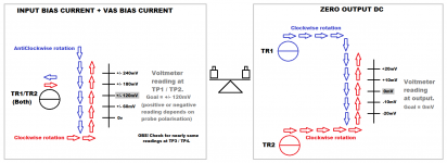
Guess its nearly same process as with VSSA amp and maxlorenz can maybe confirm that, it was nearly impossible go in 0-5mV area without having two DMM connected at same time as suggested in manual, also i made below visual for VSSA amp to help understanding under calibration.
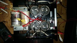
Another thing looking your build stumble over those bypass caps on power bank looks very small and wonder if their effect is measured in situation, because if not recommendation seems for audio gear either do not bypass to stay clear of new impedance peaks in the problematic region of 1...10Mhz or go on the "too large" side. More on the subject over this thread and think especially post 10 and 20 have good explanation and visuals http://www.diyaudio.com/forums/powe...ing-psu-capacitors-effective.html#post1566979.
Attachments
Until you wake us up 🙂
Another thing looking your build stumble over those bypass caps on power bank looks very small and wonder if their effect is measured in situation, because if not recommendation seems for audio gear either do not bypass to stay clear of new impedance peaks in the problematic region of 1...10Mhz or go on the "too large" side. More on the subject over this thread and think especially post 10 and 20 have good explanation and visuals http://www.diyaudio.com/forums/powe...ing-psu-capacitors-effective.html#post1566979.
More concern is about grounding scheme...
It seemed to me, from the picture, that there were multiple grounding points, instead of one star ground...I may be wrong thou...
Best wishes,
M.
More concern is about grounding scheme...
It seemed to me, from the picture, that there were multiple grounding points, instead of one star ground...I may be wrong thou...
Best wishes,
M.
No hum and fantastic sound. I will order some more. I do not like starground but bus.
THAT would be a useful comparison, because the F5T is highly regarded and widely known and used.Looking forward to your review then 🙂
F5 turbo vs FO 1.4 !
Cheers!
- Home
- Vendor's Bazaar
- First One - mosFET amplifier module