G'day.
I'm wanting to build a low pass actuve filter with maybe 4th order with a cutoff frequency around 22Hz. ie. Full output from 16Hz-20Hz, then declining in output over the 1st octave by 24dB, and so-on at higher frequencies.
The purpose is to add a 2nd smallish subwoofer to my home theatre that only produces significant output in the first octave. Without this low pass filter, the 2nd subwoofer is just adding more bass in the mid-bass and above range.
I want to fill out the 1st octave only by progressively filtering out higher frequencies that are already well produced, then raising the volume.
The idea is that instead of having a 22Hz 4th order filter order will compensate with the rising sensitivity of the subwoofer (with rising frequency), to produce a flatter frequency response (room issues not included).
I've been reading up on filters but am no expert.
Looking for suggestions (or off the shelf modules, PCBs etc). I don't intend on reinventing the filter, just implementing the best one for the application.
Last edited:
You could do this with a few biquads implemented in an op amp based circuit. If i had 20 bucks and wanted this, that is what I would do.
BUT. If you can spring the cash for a miniDSP then do yourself a favour and go that way.
Silicon chip published an active crossover and DSP last year that would eat this for breakfast.
May 2019 - Silicon Chip Online
But then of an biased 😉
BUT. If you can spring the cash for a miniDSP then do yourself a favour and go that way.
Silicon chip published an active crossover and DSP last year that would eat this for breakfast.
May 2019 - Silicon Chip Online
But then of an biased 😉
miniDSP would be a nice way to do it indeed. Another of the shelf option could be a Behringer DCX2496 or something similar.
A bit more DIY is FreeDSP.
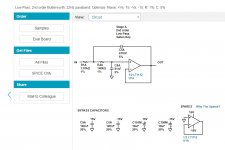
Or if you up to some prototyping on a Veroboard, this could help you design the filter: Filter Design Tool | Filter Wizard | Analog Devices
A bit more DIY is FreeDSP.
Or if you up to some prototyping on a Veroboard, this could help you design the filter: Filter Design Tool | Filter Wizard | Analog Devices
Doesnt look like an ADAU1701, which chip is that ?Silicon chip published an active crossover and DSP last year that would eat this for breakfast.
May 2019 - Silicon Chip Online
The DSP is done in a PIC32MZ, written in C. ADC is CS5381. DAC is CS4398.
Why use a PIC? With that you can code anything your little heart desires. It is also cool to see a 5 buck chip doing all that DSP🙂
Why use a PIC? With that you can code anything your little heart desires. It is also cool to see a 5 buck chip doing all that DSP🙂
Just out of curiosity: in what aspects would the SCO project eat the Minidsp for breakfast? (Do not worry to be outspoken; I am not a Minidsp fanboy)
Is it the software or is the hardware superior in your opinion? Would you be willing to share the design?
Is it the software or is the hardware superior in your opinion? Would you be willing to share the design?
The intent of the statement was that the Silicon Chip project was made exactly for driving a subwoofer and high range as an active crossover.
It if this that it would "eat for breakfast".
- crossover
- delay
- many biquads
--stereo or bridged output for sub
Not special really, but made for the job.
Aside: i have also used a lot of the analog devices kit and it works fine.
Indeed the user interface for the Silicon Chip project is a cut and paste of an ADAU1442 based crossover I use at home.
Sorry for any vagueness in my above post.
That said the THD of the Silicon Chip crossover is very low indeed....
Last edited:
Excuse my ignorance but is a biquad an opamp?
And who makes / sells the MiniDSP that's mentioned in these posts? Links?
PS - Silicon Chip has been around for decades. I remember flicking through their pages 20+ years ago. I thought they went belly up some years ago because of the loss of print magazine sales, but either I was wrong, or they were revived to compete in the Internet age.
A biquad is the basic building block of a filter in a digital signal processor when implemented in IIR.
Typical functions are lowpass, highness, parametric EQ, shelving etc.
Look up minidsp.com on the Interwebs. If you want a powerful DSP at a good price it would be hard to go past.
Silicon chip is the one real surviving australian electronics mag
Typical functions are lowpass, highness, parametric EQ, shelving etc.
Look up minidsp.com on the Interwebs. If you want a powerful DSP at a good price it would be hard to go past.
Silicon chip is the one real surviving australian electronics mag
I'm leaning towards a simple analogue opamp DIY circuit. Looking up 4th order low pass filters on the Web and there are hundreds of different ways. ???
(((00)))
How do you select the right one for this application?
(((00)))
How do you select the right one for this application?
It sounds like you are learning and getting into some of the more hands on stuff. If I were you I would build this
K5570 - Silicon Chip Magazine 2 Way Active Cross Over Kit - Altronics
Not the world's most complex, but it will work and for 20 bucks you will learn a heap. Can't go wrong.
You can then choose if you want to get more fancy from there....
K5570 - Silicon Chip Magazine 2 Way Active Cross Over Kit - Altronics
Not the world's most complex, but it will work and for 20 bucks you will learn a heap. Can't go wrong.
You can then choose if you want to get more fancy from there....
Thanks but that xover is more suited for speakers with xover points selection in the mid-treble range.
I actually build a more complex kit from altronics called Sub bass Processor (several years ago) with 4x pots, low pass, high pass, and parametric single band eq.
Great to play with and modify but is a 2nd order low pass with lots of limitations. I've been modifying it to suit my needs better but still not ideal.
That's why I'm now looking for 4th order Low pass adjustable from 20Hz.
When I look at Analog Devices site that was recommended above, there are so many ways of doing this but I lack the knowledge of what the pros & cons of each type (apart from slope shape required).
I often use a state variable filter. The one attached was done for a single rail application so uses a virtual earth - but works equally well in a dual rail application.
Sheet 1 has a stereo pair of filters.
View attachment AXO Sheet 1.pdf
The frequency is set by R42, 43, 44, 45 / C27, 28, 29 and 30
Freq = 1/(2 * pi * R * C)
20Hz would require C = 560 or 680nF and 12K resistor or similar scaling, eg 150nF and 48K (might get a little noisier due to high R). Mind you, 20Hz is unlikely to actually deliver any usable output... this will all be subsonic and much better at breaking drivers than delivering audible output. Especially with a 4th order XO.
The second sheet sums the sub to mono, and generates virtual earth. I am expecting you wouldn't need this.
View attachment AXO Sheet 2.pdf
If you built the sub processor I am thinking of, then you would also have the ability to add some boost (was there a parametric in there too?). If you are at that level, I would be circling back and looking at active solutions again.
this can be implemented as:
Last edited:
Fascinating circuit. Thanks for sharing. I started reading up on this type of circuit after your post to make sense of it.
Some questions: Is that other board a switch mode power supply or a Class D amp?
What's the purpose of the input inductor series with capacitor? Bandwidth control?
Finally, are the 4 1st order filters better than running two x 2nd order filters with a regular filter?
Finally, what do you suggest I use to simulate circuits for free? I used to use Tina-Ti which was pretty easy but limited to their chips
The other board is a class D amp.
The inductor is just there to help reduce any RF interference. It is a bead inductor. Omitting it is no big deal, it is just "belts and braces" protection.
This is not really four first order filters as they live in a feedback loop. I would not say "better" or "worse" just different. This circuit neatly delivers high low and bandpass outputs which I find handy.
I have built a lot of these and am comfortable with them - but that does not make it particularly special.
I don't often simulate. I have used LTSPICE recently, and in fact stuck this circuit in there to convince myself that the standard resistor values I have plugged in are OK and don't impact on the system performance. I am so far from a SPICE expert it isn't funny, and usually do an awful lot of swearing and cursing before I get a simulation running.
I find with things like standard filters etc, simulation will rarely tell yo much that you don't already know. (but asking "will shifting these resistor values +/-10% screw up the response IS worth simulating).
- Home
- Source & Line
- Analog Line Level
- First Octave Low Pass Subwoofer Filter Suggestions