I wonder. How may I get boards..
I wondered when you would ask that question..
The answer to that is ...make your own.
I have been drawing them out on the board directly, but now
I want to go "pro". with the artwork I have and a laser printer/
clothes iron we can do the "PCB toner method"...google it..
MJL's muriatic acid (HCL + peroxide) method
works sooooo good
 now I am going to try his actual board making method
(a few more hints would be helpful).
OS
Easy and fun (for now )
Here's the page that covers it all. Tom is a member here.
Other tips:
I use steel wool in two directions to clean the copper then lacquer thinner to make it perfectly clean. Acetone works too, but stay away from stuff like mineral spirits (Varsol) - I think it leaves a film.
Put the board on a smooth piece of plywood and line up the transfer over it.
I leave the clothes iron just sitting on it for 5 minutes or more, but then most of my boards are small enough to be completely covered by the iron. After it good and hot I rub it really hard with the iron. Lots of heat, lots of pressure.
Using the paper recommended gives great results. Don't be afraid to really get it hot - it may sizzle when you put it in the water. If the toner is not sticking to the copper it's either you didn't clean the copper well enough or you didn't use enough heat and pressure or both.
Let the paper soak for a few minutes in hot tap water then peel the paper off. I clean the paper and residue off the board with one of those plastic kitchen scrubbing pads.
Good luck
) Here's the page that covers it all. Tom is a member here.
Other tips:
I use steel wool in two directions to clean the copper then lacquer thinner to make it perfectly clean. Acetone works too, but stay away from stuff like mineral spirits (Varsol) - I think it leaves a film.
Put the board on a smooth piece of plywood and line up the transfer over it.
I leave the clothes iron just sitting on it for 5 minutes or more, but then most of my boards are small enough to be completely covered by the iron. After it good and hot I rub it really hard with the iron. Lots of heat, lots of pressure.
Using the paper recommended gives great results. Don't be afraid to really get it hot - it may sizzle when you put it in the water. If the toner is not sticking to the copper it's either you didn't clean the copper well enough or you didn't use enough heat and pressure or both.
Let the paper soak for a few minutes in hot tap water then peel the paper off. I clean the paper and residue off the board with one of those plastic kitchen scrubbing pads.
Good luck
Go buy the paper at staples.. have them print it ,or find a friend who has laser printer..etc, be resourceful for the info is now available.
Wait till 1/1/09 to get the artwork on my WWW link..
(all..schema, parts placement, BOM,instructions,and board in one
ZIP .."FA1.zip")
I want to "neaten" the CCS on FA1 (found a much more streamlined and compact way to do it with FA3 (same CCS).
I have mine (FA3) already on a CD, ready to go..
It took a lot of work..
Once you get this you can also make preamps, chipamps,etc.
You can pretty much go solo..
There are enough schemas and projects on my WWW to
make a project a week until the day I die..
OS
Attachments

Look for a copyshop or an Internet Café. You can use their laser printers or you can print with any printer you have and copy your printout on their photocopiers, which work on the same principle as laser printers.danielwritesbac said:What if no laser printer?
pacificblue said:Look for a copyshop or an Internet Café. You can use their laser printers or you can print with any printer you have and copy your printout on their photocopiers, which work on the same principle as laser printers.
Good idea man!
ostripper said:. . . Once you get this you can also make preamps, chipamps, etc.
. . .
I think that I got the etcetera already: http://www.diyaudio.com/forums/showthread.php?postid=1698835#post1698835 The (non-decorated, not shown) model/sample unit is doing 123wpc@4R right now.
ostripper said:Go buy the paper at staples.. have them print it ,or find a friend who has laser printer..etc, be resourceful for the info is now available.
Wait till 1/1/09 to get the artwork on my WWW link..
(all..schema, parts placement, BOM,instructions,and board in one
ZIP .."FA1.zip")
I want to "neaten" the CCS on FA1 (found a much more streamlined and compact way to do it with FA3 (same CCS).
I have mine (FA3) already on a CD, ready to go..
It took a lot of work..
Once you get this you can also make preamps, chipamps,etc.
You can pretty much go solo..
There are enough schemas and projects on my WWW to
make a project a week until the day I die..
OS
I'm wondering. . . On the topic of Frugal, it occurs to me that BTL output could help prevent ac from the speaker return like from polluting the 0v; and, if using lower voltage, it could reduce the power circuits cost$ as well. This thought occurs because of the luxury vs pricepoint of the output transistors that you have illustrated.
it occurs to me that BTL output could help prevent ac from the speaker return like from polluting the 0v
On both my working amps (FA1/2) the zoble goes to the board star ground and the board star and the speaker return
(16ga separate wire)
go to the main chassis star ground. NO hum (ear to speaker)
AT ALL (no turn on or off thump as well , good CCS).
OS
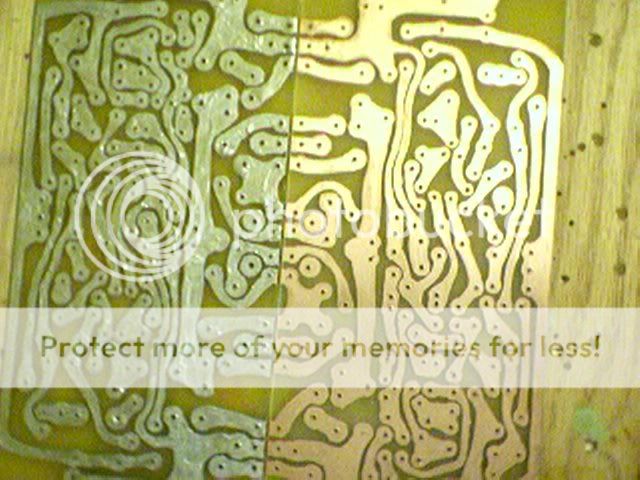
Here is PCB to print / photocopy.. 0 errors
(below)
Attachments
ostripper said:
On both my working amps (FA1/2) the zoble goes to the board star ground and the board star and the speaker return
(16ga separate wire)
go to the main chassis star ground. NO hum (ear to speaker)
AT ALL (no turn on or off thump as well , good CCS).
OS
Here is PCB to print / photocopy.. 0 errors
(below)
Oh, thank you!
What I was talking about is the difference between "grounding" the speaker onto the power star or a bridged amp "driving" the speaker neg. The AC that I was talking about is audio sent to the speaker comes back.
What you refer to is back-EMF. That does however not affect the ground, but returns to the amplifier output. That is one reason for NFB in amplifiers.
Some people put resistors in parallel to their speakers to convert the back-EMF energy into heat. Pity that resistors don't know the difference between back-EMF and output power. So they also convert part of the power into heat that the amplifier has just produced to drive the speakers. And they decrease the overall impedance, thus making the amplifier work more for the same SPL.
Some people put resistors in parallel to their speakers to convert the back-EMF energy into heat. Pity that resistors don't know the difference between back-EMF and output power. So they also convert part of the power into heat that the amplifier has just produced to drive the speakers. And they decrease the overall impedance, thus making the amplifier work more for the same SPL.
The AC that I was talking about is audio sent to the speaker comes back.
Just 2 reversed biased "clamp" diodes at the output
(like for a relay driver)
will kill EMF ...but I have run without and no problems..FA1/2..
On my HT sub I have them because it is massive (10lb magnet
peerless 12" monster) and I wanted to be safe..
OS
ostripper said:Just 2 reversed biased "clamp" diodes at the output
(like for a relay driver)
will kill EMF
No, they won't. They will protect your amp from too much back-EMF, which you may get, when you run square waves, needle pulses or similar signals that are more like switching than like sinusoids.
During normal operation back-EMF will always be lower than the preceding amplifier output signal. Therefore the diodes cannot counteract it. This type of back-EMF will not harm the amplifier, only the audible signal. One design that tries to address this topic is Graham Maynard's GEM. Others try it with tight feedback or by using the actual cone movement through secondary voice coils as feedback signal.
If you actually find a way to "kill EMF", you may become a rich man. Innumerable engineers have been addressing this topic for decades, because it not only presents problems in audio, but also much more seriously e. g. in motion control systems.
The speaker will have to shove back the rail voltage+0.6V before those diodes will work. Most speakers I imagine are damped well enough that it takes some power to build that energy up in resonance.
For some amplifiers, back-EMF can trigger oscillation but a clever designer should be able to do something about this.
Well, wait. Say a speaker resonates at about 500Hz. Get it resonating with a 500Hz sine wave at maximum power, then while the wave is at it's positive crest, suddenly bring the output down to negative rail. The speaker will already be moving against this, and so you will have twice the rail-to-ground voltage across the positive output devices. With 120V devices this shouldn't be a problem. I imagine this kind of thing plays hell with feedback so you'll get transistors in saturation (something that often leads to oscillation in some circuits).
In this extreme case, the diodes do protect the amplifier, as the rail-to-ground voltage cannot exceed -0.6V. Actually the case does not need to be this extreme. I would say that the diodes are worth it.
I would leave the diodes in just to be sure, you never know if they might help. Normal music doesn't contain extreme stuff like this but there's also electronic music... I don't know how much thought electronica composers put to what can wreck a speaker or amp. I would not cut corners under the guise of which band you think will be played most on them.
- keantoken
In my opinion, there's too much concentration on the topic of this signal and not enough concentration on where it goes. I'm not particularly concerned over the durability of the output on such an excellent design; however, I'm quite concerned about the feedback.
Here's my problem with it. In a non inverting amplifier, the ac signal present on the speaker ground cable gets into the inverting input. If this is done on a system that has an NFB cap, the already questionable component has an unnecessary workout. And, no matter where that signal goes, I see it having to be rectified via capacitors rather than diodes.
To make it clear, I don't see a problem with the signal as it relates to the speaker + jack, but rather I see it as a problem when, after the speaker and crossover have distorted the amplifier signal, the problem relates to the speaker - jack.
You need only solve one of the contact points in order to keep the problem from making a complete circuit. The speaker + jack has the proper signal were it is supposed to be. Its just fine that way. The speaker - jack sends the wrong signal into the amplifier's 0v line, where it ends up at the NFB cap and the power caps.
I'm not an expert, but here's a guess. Instead of rectifying this heavy amperage signal with the power caps alone, use a capacitance multiplier (or something similar). And, instead of allowing that signal to cross the NFB cap, use a buffer/sensor circuit instead. Since the unwanted signal has effect at the baritone and lower, the much smaller caps on the buffer/sensor NFB do not pass that signal. During the operational bandwith of the NFB sensor, if the "barrier cap" or some large RC's are used to protect amplifier power, the remaining part of the spectrum is protected. Thereby the unwanted return signal is at least decreased by a factor of 40 reduction against it getting into the NFB. The existing design already has the path of least resistance as the power star ground where the capacitance multiplier (or something similar) is the death of the unwanted signal, now that it can't go anywhere else. In other words, don't break the circuit, break the signal instead. Rectify back-EMF.
That was my best guess. Am I rich yet?
danielwritesbac said:
Here's my problem with it. In a non inverting amplifier, the ac signal present on the speaker ground cable gets into the inverting input. If this is done on a system that has an NFB cap,
Hi Dan,
When you take steps to layout and execute the ground scheme properly, this does not happen (to a degree where it will make any audible impact).
Using sensible ground layout - return speaker ground as close as possible to the power supply smoothing caps and isolating the input (both the inverting and non inverting) from the common star ground with a low value resistor will make all the difference in the world.
This has worked very well for me on several amps:
Attachments

That looks good!
Well, except that you might want to look at AndrewT's quote and answer starting here: http://www.diyaudio.com/forums/showthread.php?postid=1678237#post1678237
What do you think of that?
Well, except that you might want to look at AndrewT's quote and answer starting here: http://www.diyaudio.com/forums/showthread.php?postid=1678237#post1678237
What do you think of that?
there's no conflict there.
MJ,
could you consider adding a safety note to your diagram to show how a kA of fault current can pass from the Audio Ground to Safety Earth until the mains fuse ruptures and the arc extinguishes.
Daniel,
you're a hopeless case. I re-read your post155 and still can't find a sense of what your are trying to describe.
AndrewT said:there's no conflict there.
MJ,
could you consider adding a safety note to your diagram to show how a kA of fault current can pass from the Audio Ground to Safety Earth until the mains fuse ruptures and the arc extinguishes.
Hi Andrew,
I have been meaning to update that drawing with opposing bypass diodes across both the isolation R's.
Thanks.
In the meantime, the safety earth is still a solid, mechanical connection to the metal chassis.
Attachments

AndrewT said:. . . I re-read your post155 and still can't find a sense of what your are trying to describe.
Alternative to a bridged amplifier. Since I don't like BTL sound anyway, and its not supposed to be a bridged amplifier. . . well, yes, you're entirely correct. That post makes absolutely no sense.
- Status
- This old topic is closed. If you want to reopen this topic, contact a moderator using the "Report Post" button.
- Home
- Amplifiers
- Solid State
- First discrete amp, Need help with NTE 390, 391, 375, 398, and BD140, 139 project