OK that gives me enough information to calculate the current draw through each section of V2 to be 1.04 ma which is just right for a 12AX7. Now what is the voltage at point "D" and I will do the same for V1. While you are at it post the voltages for A,B,C, and D
I'm at work right now but If I recall correctly, the voltages were:
A: 290
B: 287
C: 267
D: 266
I could be wrong, I can take the measurements again in about 5 hours 🙂
A: 290
B: 287
C: 267
D: 266
I could be wrong, I can take the measurements again in about 5 hours 🙂
OK
Make the voltage measurments and post them. Then sence you are still having gain problems I think you need a signal source other than your guitar. One suggestion is to download a program called "Visual Analyser" (free), and run a shielded cable from the sound card in your computer to the input of your amp. This will allow you to set up a 1 Khz standard tone. Then you can go in and make some AC measurments with your meter and hopefully find out where you are losing signal. This is called using the computer for your stimulis and the meter for your measurment. Very powerfull tool! This will be usefull to you in all projects. By the way, looks like the first tube is drawing about .7 ma. plate current and the second tube about 1.04 ma. This is good because a 12ax7 max current is 1.5 ma. per section. I dont think there is anything wrong from a DC perspective, now we need a way to check out the AC signal path. Let me know.
Bob
If I have a sine-wave generator on my ipod can I just use that? It'll be a lot more portable!
I'll post voltages tomorrow for tubes and power supply. Thanks for the help!
So those bias currents you calculated should yield sufficient gain?
What should I expect to see as acceptable voltages and what should I set the output voltage of my signal generator to?, about 0.02 volts?
Thanks again.
I'll post voltages tomorrow for tubes and power supply. Thanks for the help!
So those bias currents you calculated should yield sufficient gain?
What should I expect to see as acceptable voltages and what should I set the output voltage of my signal generator to?, about 0.02 volts?
Thanks again.
Last edited:
Yes The I pod idea will work. Turn it down low, like way low, and you should be able to drive the amp as much as it will take. The pre amp tubes are OK DC wise, and should amplify a lot. Typical levels measured at the junction of C2 and C3 should be like 30 Volts AC. Does your meter measure Volts RMS? This point in the circut should have no DC on it so you will just be measuring signal. Another spot you could measure down stream is the center tap of the volume control. No DC here either. Let's get that far and re-group. We havent even talked about the EL84 yet. Don't stay up till 3 working on it 🙂
I'll take them tomorrow, I have a nice full day 🙂
Drum tracking AND amp debugging, awesome!
I'll get those measurements after breakfast and post them here.
Drum tracking AND amp debugging, awesome!
I'll get those measurements after breakfast and post them here.
I figured out the whole issue... I forgot to run a 2nd connection from the V3 to the tone stack, and then I had the resistor hooked up wrong (there was about 90V or so of DC on the master pot! I fixed all these issues today, and increased the size of the bypass cap and reduced the anode resistor of the first stage from 220to 100k. Overall it sounds great with a tad of 60Hz hum.
The hum is strange, when I increase the gain it does not increase, and when i increase the master it doesn't increase. I don't know where it could be coming from.
The hum is strange, when I increase the gain it does not increase, and when i increase the master it doesn't increase. I don't know where it could be coming from.
Very Cool--- You might try a hook up called elevated DC on the filiments. Search the forum. Perhaps try grounding the outer cases of the pot's and see if it is better. Uh-- perhaps somone else has more ideas. I am glad that you have gotten it this far. If you have a chance, post pictures of the cab. I do combo amp's too. Show me your's and I will show you mine 😱
Alright! I wanna play guitar for a while now, I don't know if I want to open it back up again just yet. It does sound great 🙂.
My filaments are elevated to about 100v DC because of my cathode follower. Also, my elevation circuit doubles as my cap bleeder circuit!
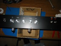
I'll take pictures soon, I like how the tolexing came out, but it took a while and was frustrating.
My filaments are elevated to about 100v DC because of my cathode follower. Also, my elevation circuit doubles as my cap bleeder circuit!
I'll take pictures soon, I like how the tolexing came out, but it took a while and was frustrating.
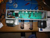
Here are the guts
So I take it you are a guitar player, and not a bass player?
- Status
- Not open for further replies.
- Home
- Amplifiers
- Tubes / Valves
- First amp build... help please!