Hello,
This is my first time designing a two way speaker with bass reflex, I have made a couple of full-rangers in the past, but this is my first time trying to put together a crossover.
The drivers I am gonna use is a dayton audio TCP-115 4ohm and a dayton audio Dayton Audio ND25FA-4, in a 4 liter box with a slot port tuned at 57hz (i wanted to make it a bit smaller but i couldn't really.
The crossover is a 3-part one or the tweeter and a 2part one for the woofer. I am trying to keep cost down since i wouldn't want for the crossover to cost more than the drivers.
How does it look to you, should I change something? Would i need a baffle step correction filter ( baffle width is 20cm)?

Vituixcad does offer you the opportunity to simulate baffle effects. This will bring you much closer than guessing so I would recommend it in this case.
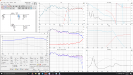
Also, I would change the vertical scale on the response plot.
Also, I would change the vertical scale on the response plot.
Where you use 10dB per major division I'd use between 1 and 5, depending what stage I was at.
Your circuit looks fairly standard, nothing much to say. Your values and your choice of how to filter the drivers is less clear but it does not look like a problem.
Your circuit looks fairly standard, nothing much to say. Your values and your choice of how to filter the drivers is less clear but it does not look like a problem.
Is there any substantial advantage of using something more "advance" circuit wise. I made some changes since baffle step effects seem to reinforce heavily the area between 1-2khz. My bigger worry is about phase, impedance and driver alignment problems, but i suppose they look ok.
Attachments
Last edited:
Yes it looks OK. Since you are using the single measurement per driver style, it is difficult to say which way would be better with phase. It is difficult to say whether you will be happy, I would expect to do some tweaking.
I am not really sure what you mean by "which way would be better" are you talking about inverting the polarity of the drivers ? What should I try to hear when evaluating the phase?
You should try to hear that the tone is balanced, that you have a clean connection between the drivers rather than a dip or a peak. This is not only because of the direct sound but also because of the reflected sound.
you have done a nice job on your crossover so far. It is not done, but you are getting closer.
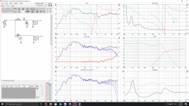
I can not tell if you applied the diffraction response to the drivers in post #6, or are you simply showing the baffle diffraction effect?
If the diffraction effect has been applied, then the +3 dB rise in response at 100 - 200 Hz will give your speakers a pleasant warm quality.
If the diffraction effect has not been applied, this means you have only a 3 dB baffle step compensation. If speakers are placed near the rear wall, this may be enough, but if they are mounted out in the room (50 to 100 cm from a wall), they may sound too lean... meaning a lack of mid bass.
Have you accounted for the fact that the tweeter is somewhat closer to your ears than the woofer? probably 20 to 40 mm closer?
j.
Thanks, what steps do I need to finalize it? I have applied an attenuation of about -3db. My problem is that i cant import two drivers in the baffle effect simulator. The woofer is probably going to need a slim correction as well since it reaches quite high. The +3db rise between 100-200 is a characteristic of the woofer, i would need a notch filter to bring it down, or just up the highs and go for a smile face response. I've red thought that once you contain a woofer in a box the low bass-sub bass is going to drop about 3-6 db, this is why i havent bother to correct the response there(+ it will add complexity to the circuit). Moreover the acoustic centers of the tweeter and woofer are around 10cm afar, this is why i was asking about alignment, how would you account for that? Lastly, every time I ve made a baffle step corrector that attenuates 6db the response, I find that it completely obliterates the highs, that in combination with the fact that is going to be used on a desk near a wall, with the port facing forward, made me to only apply a 3db attenuation
... in combination with the fact that is going to be used on a desk near a wall, with the port facing forward, ...
With the speakers sitting on a desk, near a wall, you probably have enough baffle step correction. No need to change that.
The distance I was talking about is not the vertical spacing (the y-direction). I was talking about the z-direction. The tweeter voice coil is almost flush with the baffle, but the woofer voice coil is behind the baffle. This means that when both drivers get a signal, it takes a longer time for the woofer sound to reach your ear than the tweeter sound, because the tweeter is a little bit closer.
VituixCad assumes both drivers are the same distance from your ear, unless you adjust the simulation. If you go to the "driver" tab, you will see a box at the bottom called "delay". You can enter a delay value in micro seconds for the woofer. 3 micro-seconds is about 1 mm. For your two drivers, the easiest way to estimate the woofer delay is to measure the distance (the depth) of the woofer dust cap compared to the tweeter dome. Just looking at the drawings, I estimate 80 micro-seconds (28 mm)... but you should make your own estimate.
When you enter this delay in VituixCad, it will change the system response, and you will have to readjust your crossover.
Unfortunately I dont have the parts on hand yet. But if we assume that the woofer voice coil is located in about the middle of the driver then that's 30mm, i would argue that the convex morphology of the tweeter dome might give it about 6mm offset on the opposite direction so maybe a little more than 30ish mm? or 90ms. I see that this affects almost exclusively the crossover point and brings the response between 1-3k. I am more concerned about the dip around 2.5k, but there isnt much i can do since its inherited by the tweeter's response. Also, chould i combat the z-axis offset by just placing the drivers on different depth on the baffle ?
P.S this is, free air response so the mid bass section is going to be reinforced by the bass reflex.
P.S this is, free air response so the mid bass section is going to be reinforced by the bass reflex.
Attachments
Last edited:
Your tweeter filter resonance is now in the 3-4kHz region. You might want to try the peak a little lower. First try increasing the value of one of the tweeter components.
So would something like that be better? I wasn't able to lower the resonant point below 3k with the previous circuit. This brings it all the way down to 1.3k but messes with the phase and the impedance a lot. What is the reasoning behind wanting to bring the resonant frequency lower than 3-4khz?
Attachments
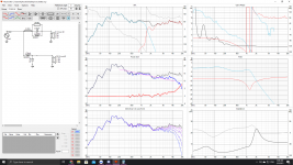
You asked about filling the 2k5 dip, that is the intention.
I have a question, why does your tweeter response have the dip above 2k and the peak below? Did you measure this in a reflective environment?
I have a question, why does your tweeter response have the dip above 2k and the peak below? Did you measure this in a reflective environment?
Ah that was the point. I haven't made any measurements myself, this is the response that the manufacturer, Dayton audio, provides. I woulsing know what causes this. I suppose
it would be best if I where to cut off the Tweeter before the dip and eliminate it all together, but I would need a different woofer then that reaches higher.
it would be best if I where to cut off the Tweeter before the dip and eliminate it all together, but I would need a different woofer then that reaches higher.
- Home
- Loudspeakers
- Multi-Way
- First 2 way speaker