I have been wondering about that tweeter response as well. It might be caused by the impedance rising from 3.5 ohm up to about 7 ohm at the resonant frequency of 1350 Hz. That can make it a challenge to design a crossover near 2000 Hz.
Attachments
Here is the first iteration of the crossover: View attachment take1.zip
And here is the measurement data for the two drivers:
View attachment TCP115-4_data.zip
View attachment 275-059--Dayton-Audio-ND25FA-4_data.zip
Also this is a new take, trying to bring the x-over point higher, the dip in the 1-2k is eliminated but the woofer messes the 5-8ish khz region with a weird peak, i am not sure how to increase the roll-off slope to a higher db per octave
.png")
And here is the measurement data for the two drivers:
View attachment TCP115-4_data.zip
View attachment 275-059--Dayton-Audio-ND25FA-4_data.zip
Also this is a new take, trying to bring the x-over point higher, the dip in the 1-2k is eliminated but the woofer messes the 5-8ish khz region with a weird peak, i am not sure how to increase the roll-off slope to a higher db per octave
It seems the issues with the tweeter lower frequencies are mostly directional. The existing measurements are showing that following the response may not be entirely the right thing to do.
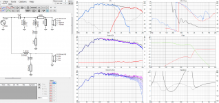
I've added simulated diffraction. This also contributes to axial variations. I'd suggest you consider rounding your edges. It may also help to make your response more flat.
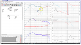
Here is an attempt at the crossover. The first screenshot, left middle plot, blue trace.. speaker power is roughly following the pink suggested target. The RLC on the tweeter seems to help with the lower peak.
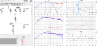
The second shot shows the result off-axis at 20 degrees. This is meant to show what you'd get if you listened with the speakers at an angle from your listening position, maybe crossed in front of you. Things are much more smooth looking.
I've added simulated diffraction. This also contributes to axial variations. I'd suggest you consider rounding your edges. It may also help to make your response more flat.
Here is an attempt at the crossover. The first screenshot, left middle plot, blue trace.. speaker power is roughly following the pink suggested target. The RLC on the tweeter seems to help with the lower peak.
The second shot shows the result off-axis at 20 degrees. This is meant to show what you'd get if you listened with the speakers at an angle from your listening position, maybe crossed in front of you. Things are much more smooth looking.
Attachments
That looks real nice, Allen... From a response standpoint it looks like a winner to me.
I wonder how necessary that 47 mH inductor is in the tweeter circuit? That component might be a bit expensive. I have not opened the zip file, but I think I will take a look...
j.
I wonder how necessary that 47 mH inductor is in the tweeter circuit? That component might be a bit expensive. I have not opened the zip file, but I think I will take a look...
j.
That's true, it seems like the off-axis response Is better in the 1-2k region, I will definitely round the baffle edges. I wouldn't have never thought that listening off axis would ever be better than on axis and the drop after 15k is completely negligible considering that I cant really hear much above 14k. Thanks a lot for the crossover, the response here looks much better, its on completely different level. I am not sure if i can justify the added cost and complexity though i am not sure if it can even fit the cabinet. Many thanks for your time and advise.
Clearly it isn't necessary, I just ran it out of range while tweaking, it can be removed... I don't really show a crossover thinking it's final, these things are usually a long time in development, and it's not really easy for me to see from my point of view at what point of development a crossover like this is, I don't even lock my own crossovers inside the boxes. Besides, someone has to check excursion, impedance, distortion and whatever else. Then there's the tonal balance. Some like the falling response but it has to sound natural also, and this will be partly room dependent, even if it should be less so.I wonder how necessary that 47 mH inductor is in the tweeter circuit?
What I see that I added here is the diffractions, the driver offsets and the RLC circuit.
I've attached the diffraction added traces. Let me know if they don't work for you.
Attachments
Clearly it isn't necessary,
Well that is good to know... I was wondering if there was some exotic circuit topology I was not aware of. I should have guessed the truth... pretty obvious in hindsight.
I like that you utilized a resister network on the tweeter... this makes tweeter adjustments very easy to trim.
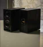
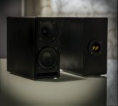
@kyrk I've made a bookshelf using the same drivers as your project but the tweeter is the waveguide version, i called them Loki, they sound amazing (F3 40Hz). Slotted port, 5 liters net.
Couple of pics:
Couple of pics:
Attachments
- Home
- Loudspeakers
- Multi-Way
- First 2 way speaker