Hello Dougie085,
Check polarity of caps, power connections,and in/out signal wiring. Maybe make sure LM3875 pins are in proper holes. Sometimes one can look at something over and over without seeing it properly 🙂
Human error vs. bad chips usually wins.
All the best,
BC
Check polarity of caps, power connections,and in/out signal wiring. Maybe make sure LM3875 pins are in proper holes. Sometimes one can look at something over and over without seeing it properly 🙂
Human error vs. bad chips usually wins.
All the best,
BC
Well the wiring is right I checked it at least 10 times. I'll check the caps. The chip I'm not sure how you could put it in wrong?
The capacitors are the same on both boards. And the chips are soldered in the same way too. So I don't think its that.
What is the DC offset in both channels?
Check Caddock resistors if they are in the right spots ( 220 and 22k)
Check Caddock resistors if they are in the right spots ( 220 and 22k)
I 'm asking about DC offset (at speaker terminals). It can't be that high.
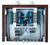
Also, I see 4 resistors on each amp board in your pics, check if thay all in proper places.
Also, I see 4 resistors on each amp board in your pics, check if thay all in proper places.
Ok well the channel that doesn't work right has a 22.0kohm resistor on the chip. The one that does work has a 220ohm resistor. This may be part of the problem. I didn't put the actual boards together my self so sorry I didn't realise those were resistors I've never seen a resistor like that. In your manual you use a 22.1kohm so the problem isn't that the other channel isn't very loud its that the other channel is far too loud. Might be where all the noise comes from as well. This makes a lot of sense now. I'll have to see if he has another one of the 22kohm but I don't think the kit came with extra's? So maybe his kit had one of the wrong resistors? I don't know I'll have to ask him about it.
I suspect that resistors may have been swapped. They should be as follows:
R1= 220R
R2= 22k
Rf (directly on the chip) 22k or 22.1k (depending on my stock at a time)
R1= 220R
R2= 22k
Rf (directly on the chip) 22k or 22.1k (depending on my stock at a time)
Do you send extra with your kit? The other resistors are correct. So this must have been the last resistor he had in the kit unless you include extra's?
At $4/pc I don't send extras. So far I also didn't make a mistake.
So how many 220R resistors and how many 22k did he have?
So how many 220R resistors and how many 22k did he have?
He had 3 of each. Which I guess he should of had 2 220 and 4 22.0k but on board 1 there is 1 220 in R1 1 22.0k in R2 and 1 22.0k on the chip. On board 2 there is 1 220 in R1 a 22.0k in R2 and a 220 on the chip.
It should be 22k on a chip, but prevoiusly you mentioned that the one with a 220ohm resistor works fine?
No the 22.0kohm one works fine the other one does not. The one with the 220ohm resistor is about 500 time louder then the one with the correct 22.0kohm resistor. I just listened to the quieter channel and it sounds like its at the right volume while the other channel I can have my source turned way down and its still very loud.
Member
Joined 2002
Dougie085 said:Ok thanks Peter!
Looks good man Keep up the good soldering 🙂 P.s Put new RCA wire in there, shielded stuff 🙂
P.s Put new RCA wire in there, shielded stuff
I also planned to mention that thing. Input and output wires all twisted together don't look to hygienic to me soundwise.
Mr. Carr's Masterpiece ?
> Shielding the wires is not needed.
Does no harm though, does it ?
Patrick
> Shielding the wires is not needed.
Does no harm though, does it ?
Patrick
let's keep the twisted pairs and add shields.EUVL said:Mr. Carr's Masterpiece ?
> Shielding the wires is not needed.
Does no harm though, does it ?
Patrick
Where would you connect the shields? audio ground, input ground/return, PCB signal ground, Safety Earth?
- Status
- Not open for further replies.
- Home
- Amplifiers
- Chip Amps
- Finishing up chipamp!