> Where would you connect the shields? audio ground, input ground/return, PCB signal ground, Safety Earth?
Star Ground ?
Patrick
Star Ground ?
Patrick
Member
Joined 2002
Peter Daniel said:Shielding the wires is not needed. Look inside that $30k preamp, twisted pairs only 😉
However there is no ac or psu in that same container, it is external. I bet if they were to put the psu internal then those wires would be more than shielded.
Jase
But in my chassis the psu is all in its own little area behind very thick aluminum walls. So I'm not so sure it would help all that much. It may though? I was going to get better wire for the inputs and outputs anyways so I may just get shielded just in case. Besides it looks pretty 😉
Better input wire
Looks like the same wire for input and output. This is not agreed to by all, but wire makes a difference.
Try some small soilid core for the input wire. There is everythging from 6/9's silver to electrolytic copper. Everyone has a fave. Somewhere around 26 -28 ga always seems the best to my ears. Twisted pair, maybe some cotton sleeving to insolate and damp the string.
If you can hear resistor brands, you can hear composition, geometrey, dielectronics, and terminations of the input wiring. I am not so sold on the importance of the output wiring. But others swear that is critical too.
Everything makes a difference, just I am not sure you can hear them.
Good job on the build! Nice kit.
George
What size resistor do you use for the LED? Probably pick one of those up today. Oh and why is it better to use such a small guage single strand wire for the inputs? I've seen this said before. Same with silver interconnects it seems that the smaller 26-28guage is better then something larger?
jleaman said:However there is no ac or psu in that same container, it is external. I bet if they were to put the psu internal then those wires would be more than shielded.
Jase, I've been building those amps for years and I know what I'm talking about: I don't even use tweested pairs.
Shielding is not needed.
Member
Joined 2002
Peter Daniel said:
Jase, I've been building those amps for years and I know what I'm talking about: I don't even use tweested pairs.
Shielding is not needed.
Yes i know peter, however im stating that its better to do it than not to do it, I TOOO built one, however i did have chassis noise, so that is why i'm telling him.
I'm not saying he has to,im stating it would not hurt.
Jase
Actually, it might hurt, as it's hard to come across decently sounding shielded cable. That's the main reason I do not use one.
What do you mean by "chassis noise"? Using shielded wire eliminated it? IME, it's the way that grounding is done not the lack of shielding that creates "chassis noise".
What do you mean by "chassis noise"? Using shielded wire eliminated it? IME, it's the way that grounding is done not the lack of shielding that creates "chassis noise".
Give it a listen
Get it working, then lsiten for a while. Then twist up some 26 ga magnet wire. I like to use two grounds and one hot. Then slip a cotton sleeving over the hot.
Braid them instead of twisted. Then listen. I would be very surprised if you did not like the sound better.
You could duplicate just what you are using now with bare magnet wire,26 ga, no sleeving and twisted pair construction. It will sound better than what you now have also.
There are some scientific reasons why smaller ga wire is better is very low power applications. But the application is rf, not audio frequency.
Better wire than magnet wire is out there. Magnet wire works fine though.
I used to use solid core output and speaker wire. That was with 100 dB efficient speakers and current delivery was not an issue. Now the speakers used require lots of current. THe stiffness 12 -14 ga solid core was just too much hassle to deal with.
George
Dougie085 said:Oh and why is it better to use such a small guage single strand wire for the inputs? I've seen this said before. Same with silver interconnects it seems that the smaller 26-28guage is better then something larger?
Get it working, then lsiten for a while. Then twist up some 26 ga magnet wire. I like to use two grounds and one hot. Then slip a cotton sleeving over the hot.
Braid them instead of twisted. Then listen. I would be very surprised if you did not like the sound better.
You could duplicate just what you are using now with bare magnet wire,26 ga, no sleeving and twisted pair construction. It will sound better than what you now have also.
There are some scientific reasons why smaller ga wire is better is very low power applications. But the application is rf, not audio frequency.
Better wire than magnet wire is out there. Magnet wire works fine though.
I used to use solid core output and speaker wire. That was with 100 dB efficient speakers and current delivery was not an issue. Now the speakers used require lots of current. THe stiffness 12 -14 ga solid core was just too much hassle to deal with.
George
ALRIGHT! Well amp is playing now! 🙂 Although still have some static noise with some radio station pickup or something. Which is still a bit strange to me. I can clearly hear what song is playing on whatever station it is too lol. But both channels are working equally. This is a very powerful amp. I wasn't expecting it to be so powerful at only 60ish watts. I can't wait till I work out the grounding issues and play it on my nice speakers rather then these cheap sanyo table top stereo speakers.
If you have problems with static or picking radio stations, installing 200-300pF cap between non inverting and inverting inputs should help.
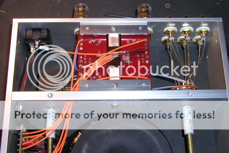
Peter, In this pic what size resistor did you use between the IEC ground and the copper wire? Also You just connect all the grounds to this copper piece rather then to the boards and what not? Like PG+ and PG- and all that. Do you also connect the ground from the RCA inputs to that spot? It looks like you just have the 2 power wires from the rectifier board running to the amp modules them selves.
Edit: Now that I look at it do you have the RCA inputs grounded at all? Looks like they are just connected together as far as the ground part goes.
Edit: Now that I look at it do you have the RCA inputs grounded at all? Looks like they are just connected together as far as the ground part goes.
WHERE IS THE SAFETY EARTH?Dougie085 said:Peter, In this pic what size resistor did you use between the IEC ground and the copper wire? Also You just connect all the grounds to this copper piece rather then to the boards and what not? Like PG+ and PG- and all that. Do you also connect the ground from the RCA inputs to that spot? It looks like you just have the 2 power wires from the rectifier board running to the amp modules them selves.
Edit: Now that I look at it do you have the RCA inputs grounded at all? Looks like they are just connected together as far as the ground part goes.
See what the smallest cap you can get away with is, following Peter's advice...
Some other solutions, install a piece of L bracket closer to the input sockets, put the selector there and extend the shaft.
Or shielded wires for the input wireing.
As Mousey said, get some heatshrink for those exposed live terminals.
Some other solutions, install a piece of L bracket closer to the input sockets, put the selector there and extend the shaft.
Or shielded wires for the input wireing.
As Mousey said, get some heatshrink for those exposed live terminals.
Well thats not actually my chassis. I don't have selectors or anything. As far as exposed live terminals I'm guessing your talking about on the IEC.
AndrewT said:WHERE IS THE SAFETY EARTH?
It is connected where bottom cover is installed.
Dougie085 said:So you don't think its an issue with grounding then?
Dougie085 said:Peter, In this pic what size resistor did you use between the IEC ground and the copper wire? Also You just connect all the grounds to this copper piece rather then to the boards and what not? Like PG+ and PG- and all that. Do you also connect the ground from the RCA inputs to that spot? It looks like you just have the 2 power wires from the rectifier board running to the amp modules them selves.
Edit: Now that I look at it do you have the RCA inputs grounded at all? Looks like they are just connected together as far as the ground part goes.
In most cases the wiring you did works fine. However in some setup it was producing hum and I switched to grounding scheme like in a picture. There is a thick copper wire connecting both channels output grounds (OG). The ground wires from rectifier board are connected centrally on that wire (either 2 or preferrably all 4). The RCAs grounds connect to SG points on each board.
In a picture RCA grounds go first to the switch (for mute option) and then to the boards.
When you don't get hum but static and radio frequency pickup, 300pF cap usually is all you need.
The resistor between IEC ground and the circuit ground is 10R. After bottom cover is installed, IEC ground is connected to chassis.
- Status
- Not open for further replies.
- Home
- Amplifiers
- Chip Amps
- Finishing up chipamp!