A while back in my "what to do with these parts" thread, I started building a 6l6 6x ppp amp. I didn't have a windows PC to do sims on, so that design was essentially terrible. I redesigned it with a dc-coupled preamp (SRPP into LTP) cap coupled into the grids of the 6l6gc banks. In simulation, the preamp was good beyond 10Mhz, and obviously down to 0hz. According to LTspice, including resistances of transformers, I can get around 105v peak-to-peak into 8 ohms @ 440hz. Probably much less in reality, but half of that is still quite good! Currently running it with feedback off, sounds great!
Dead quiet with a load on the input, still extremely quiet with the inputs open! I haven't clipped it before the speakers started clipping first. I'd like to figure out a way to bench test the RMS output without a scope, someday. In any case, I can get resonances to propagate under the floorboards and induce sympathetic vibrations in the crawlspace, also audible outside of house. Perfect for a high/mids driver monoblock, or a general purpose power amp. I wish I could build two! Sounds better than my kenwood ka3500 and compares favorably (apples/oranges) to the yamaha natural sound power amp we have.
Running a bit warm, still need to optimize the bias circuit. One of the original 6p3s-e used for testing started redplating, it was replaced. This thing runs them like 6L6GCs, and they seem to take it. Screens are dim, no red plate in dark room.
Here's some pics and the spice file (with .INCs). Any comments, improvements, etc. are welcome. You are welcome to use this design or its improvements for any non-commercial use, assuming you'd want to. Commercial use of this design requires contacting me. It's not anything special anyhow. I won't be posting PCB layouts, it's all point to point. Parts were around $300, can't remember it's mostly stuff I didn't need from other projects.
Attachments
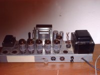
Incidentally, I am not entirely sure about the inductances on the OPT in the spice file. 689 watts (105squared/twice8) is so ridiculously high that I am sure I mucked that up. In any case, the OPT is only rated for about 100w "guitar" so even if the amp can swing it the OPT will probably melt. Primary impedance is 1700, DCR is 19 and 22 to center tap from each side respectively. Oh that's a quarter in the front view, for scale.
Incidentally, I am not entirely sure about the inductances on the OPT in the spice file. 689 watts (105squared/twice8) is so ridiculously high that I am sure I mucked that up. In any case, the OPT is only rated for about 100w "guitar" so even if the amp can swing it the OPT will probably melt. Primary impedance is 1700, DCR is 19 and 22 to center tap from each side respectively. Oh that's a quarter in the front view, for scale.
I'm afraid you got the math wrong. 105 Vp-p has to be divided by 2 and then by the square root of 2 to get the RMS voltage which for you is 37.12 V RMS. Square that and divide by 8 and you get 172 Watts - not humble for a tube amp but not 689 by a long shot.
G²
Was aiming for 100W, glad I got more. The 689 seemed to be a math error, since the equation I got for RMS power was (Vpk^2/(load*2)). I probably have an erroneous equation! I calculate approx 154w pd, so any more than that would be nonsensical. The transformer can't handle much more in any case!
Actually, that's comforting since the result is within my current OPT's spec. I was quite confused w/regards to the RMS wattage based on my equation!
Actually, that's comforting since the result is within my current OPT's spec. I was quite confused w/regards to the RMS wattage based on my equation!
Just road-tested it as a keyboard amp for a local band's small show. Some hum developed after an hour or so, I think a cap solder let go. I have series-parallel tv caps (250v), which are optimized for board soldering. DC offset at input was also possibly contributing. Feedback was not engaged. No red plating or red screens. Audio power was sufficient w/ Fender Eminance in parallel with ( 16-ohm Wilder speaker alnico in parallel with 16-ohm 780W power resistor). Total system impedance was 5.4 ohms, on the 4 ohm tap, giving around 2.2K anode-to-anode impedance. Would have preferred to run a 7.5-8 cab, what have you). Clipped beautifully (asked keyboardist for transient clip in second set...). Plugged guitarist into it after show, he seemed to enjoy it.
Hum developed late in the show (last couple songs)...I believe a cap let go 🙁. Rk for output stage is still 65R instead of 100R, since I had 20min warning that the amp was needed!🙂
Hum developed late in the show (last couple songs)...I believe a cap let go 🙁. Rk for output stage is still 65R instead of 100R, since I had 20min warning that the amp was needed!🙂
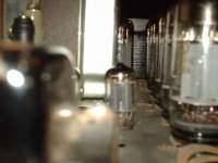
Nice work. You might check to see what the output tube bulb temperatures look like- if you're running this bad boy hard, you'll want more air flow around them than it looks like you have.
Bulb temp is probably over 100C, and the transformers are running at max (not too hot to touch, but just barely). I don't run my heater when it's on for a bit 🙂. Forced air cooling is a final chassis addition for sure. I am going to try to fiddle the bias for cooler operation. The hum that developed was perplexing, I am hoping it was a cap that let go or Hk shielding on a preamp tube and not a DC drift issue. It's also ugly, I need to address that--It's something like 10 inches wider than a rack, so that's out the window.
The keyboardist said he had the volume on his rig not past 1.5/12. Clearly audible above the drums & bass rig. Thanks for the help!
The keyboardist said he had the volume on his rig not past 1.5/12. Clearly audible above the drums & bass rig. Thanks for the help!
- Status
- Not open for further replies.
- Home
- Amplifiers
- Tubes / Valves
- Finished the "big one"!