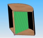
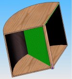
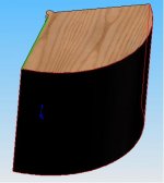
After Tom Danley's suggestion in the other thread this is what I've come up with for the final DC motor driven design
that's a 24x30" cone... each opening is 25x30" and is 60degrees from the center line of the curve
it allows for 30" of one way movement in each direction and is dipole... designed to be optimal in such an exclosure
2HP servo motor... with 300vdc and 5A.... (already bought this)
cone will be carbon fiber over foam (needs internal dampening) shooting for 1/8" thick carbon fiber epoxy resined
BB6 says 4800cm2 of cone area moving 5" one way (the suspension will allow for 22" one way) yields 133db at 10hz.... at least with a 1500 gram cone weight 😉
if I can get a stable 10+ inches you're looking at around 137db at 12hz or so in dipole...
I'm only looking for this to play to about 35hz or less...
any suggestions?
Attachments
So its the same sort of drive system as contrabass but DIY?
http://wanderkolonie.org/servo2.htm
http://wanderkolonie.org/servo2.htm
An externally hosted image should be here but it was not working when we last tested it.
mike.e said:So its the same sort of drive system as contrabass but DIY?
http://wanderkolonie.org/servo2.htm
An externally hosted image should be here but it was not working when we last tested it.
kind of... it's a different method driving the cone though
there's no rotation to linear converter and it's not a normal subwoofer.
it literally swings that piece of kevlar/carbon fiber and foam to produce very very low bass at very very high SPL's
johninCR said:Am I looking at it correctly, the green thing is your cone which will sweep back and forth?
yes 🙂 🙂 🙂
In that case,
1. Dipole will have a whopping SPL of 0db . + & - waves of the same magnitude travelling the same distance net to zero. The front of your speaker would be your dipole null. One side of your contraption needs to be in a box or separated in some fashion, and not just a divider with them both still facing the front.
2. Your cone will be traveling very different speeds depending how far the point on the cone is from the axis. I think this will cause significant doppler distortion.
3. If your motor will work like you think, wouldn't it be less problematic to drive your cone in a pistonic motion?
johninCR said:2. Your cone will be traveling very different speeds depending how far the point on the cone is from the axis. I think this will cause significant doppler distortion.
Additionally, it sounds to me (although I may have misunderstood) that your SPL calculations were done with pistonic travel in mind. In your case, however, one edge of your 'cone' is stationary. As such, the swept volume of a given displacement of one edge of your 'cone' will be half that of a 'cone' that is not stationary at one edge.
johninCR said:In that case,
1. Dipole will have a whopping SPL of 0db . + & - waves of the same magnitude travelling the same distance net to zero. The front of your speaker would be your dipole null. One side of your contraption needs to be in a box or separated in some fashion, and not just a divider with them both still facing the front.
2. Your cone will be traveling very different speeds depending how far the point on the cone is from the axis. I think this will cause significant doppler distortion.
3. If your motor will work like you think, wouldn't it be less problematic to drive your cone in a pistonic motion?
this is the problem with the CAD ... it wasn't exactly clear... there will be a type of compression panel aiming the backwave 180 degrees from the front wave... I just included the musical element itself
2. this is the same method the PG cyclone uses for servo's... so I'm not sure if this was an issue for them...
3. I can and may in fact do a simple down firing element... problem is coming up with a workable rotation to linear converter with only one "pumping" action vs. the dual action Tom's design for the contrabass... there's the very distinct problem getting the moving mass low enough this way
Construct said:
Additionally, it sounds to me (although I may have misunderstood) that your SPL calculations were done with pistonic travel in mind. In your case, however, one edge of your 'cone' is stationary. As such, the swept volume of a given displacement of one edge of your 'cone' will be half that of a 'cone' that is not stationary at one edge.
to apply a pistonic SPL calculations all you do is take the mean (center) of the moving element and how far it travels... which is 15" one way max...
this will give the you mean (average) excursion at 30" one way (this is how far the outer edge is traveling)....
ok, ive got some down-time in the next few days.
im going to hook up some of my bigger servo motors to an amplifier and see what they do... i still dont get the general idea of how the servo motor works.
if it moves back and forth like it should, ill attach some fins to it or something and see if it makes noise 🙂
im going to hook up some of my bigger servo motors to an amplifier and see what they do... i still dont get the general idea of how the servo motor works.
if it moves back and forth like it should, ill attach some fins to it or something and see if it makes noise 🙂
cowanrg said:ok, ive got some down-time in the next few days.
im going to hook up some of my bigger servo motors to an amplifier and see what they do... i still dont get the general idea of how the servo motor works.
if it moves back and forth like it should, ill attach some fins to it or something and see if it makes noise 🙂
it has to be a DC motor... just so you know...
it will make noise with a fin but you need a suspension... or play a higher note at lower volumes to keep the turning in line...
Audiophilenoob said:
to apply a pistonic SPL calculations all you do is take the mean (center) of the moving element and how far it travels... which is 15" one way max...
this will give the you mean (average) excursion at 30" one way (this is how far the outer edge is traveling)....
Nope. That will significantly understate your air moved. Back to geometry class we go.

johninCR said:
Nope. That will significantly understate your air moved. Back to geometry class we go.
hhahaha well yea haven't had math in years, it made sense to my poor math skills... I went ahead and figured it out though 😛
it's roughly 161.48L Vd one way... this is 26" around the "circle" there's roughly 27" from rest position and the opening around the edge of the circle part
I apologize for my poor math skillsIf it were me.... I would make this an IB "sub." Bass modes at extremely low frequencys(below30hz) typically are inexistant anyhow and the achieveable SPLs would be incredible.
With your existing design there will be INSANE mechanical vibrations from the unbalanced rotation. a good idea might be to put a weight on the other side to counterbalance and steady things up
With your existing design there will be INSANE mechanical vibrations from the unbalanced rotation. a good idea might be to put a weight on the other side to counterbalance and steady things up
BassAwdyO said:If it were me.... I would make this an IB "sub." Bass modes at extremely low frequencys(below30hz) typically are inexistant anyhow and the achieveable SPLs would be incredible.
With your existing design there will be INSANE mechanical vibrations from the unbalanced rotation. a good idea might be to put a weight on the other side to counterbalance and steady things up
the motor weighs on the order of 100 lbs and will be incased in concret e 🙂
the moving mass is < 2lbs likely
what do you mean by IB sub? the way I drew it with the added compression chamber on the rear to keep the waves from being close to the same plane?
how would you modify it?
IB = Infinite Baffle. You'd put in a wall between two rooms so that the front side would go into the listening room and the rear would go into the other room whatever it may be (an attic crawlspace, garage, etc....) That would isolate the front and rear waves increasing spl as frequency goes down by 12db/octave(I think) over a dipole.
You can slap as much weight on the box as you want, but at even 1lbs of moving mass if its moving 10+ inches at even 20hz there's going to be alot of inertia at work.
You can slap as much weight on the box as you want, but at even 1lbs of moving mass if its moving 10+ inches at even 20hz there's going to be alot of inertia at work.
When developing the cyclone PG struggled with keeping the fins light and strong enough.
Their solution was to use a foam-core with a carbonfibre skin, thick at the base gradually thinner towards the outer edge.
Light weight is most important at the edge, and high strength at the base.
The longer the fins the more important it is to have high strength and to keep the weight down at the same time.
Regards,
Peter
BassAwdyO said:IB = Infinite Baffle. You'd put in a wall between two rooms so that the front side would go into the listening room and the rear would go into the other room whatever it may be (an attic crawlspace, garage, etc....) That would isolate the front and rear waves increasing spl as frequency goes down by 12db/octave(I think) over a dipole.
You can slap as much weight on the box as you want, but at even 1lbs of moving mass if its moving 10+ inches at even 20hz there's going to be alot of inertia at work.
I don't know how that can be made to be practical...
maybe I can come up with an artifical dampening solution to eliminate or greatly reduce the back wave....
I wonder how much say 12=14" thick of dense foam would help... in making an "IB" effect without IB
- Status
- Not open for further replies.
- Home
- Loudspeakers
- Subwoofers
- Finished subwoofer idea.... what do you think?