The led does not light up. Not sure why it's there..maybe try adjusting the variable resistor
Have done that, no change with or without the led. The missing board should be here in a day or two, maybe that might make a difference.
r8833,
Can I trouble you to check the long black multi resistors thingy next to the AK4118 on the dac board? The board is printed 10k8 but the kit came with part labelled A472J (4.7k?). Wonder if it's causing no sound from the dac and failure to display. Thanks.
Can I trouble you to check the long black multi resistors thingy next to the AK4118 on the dac board? The board is printed 10k8 but the kit came with part labelled A472J (4.7k?). Wonder if it's causing no sound from the dac and failure to display. Thanks.
The button board came. No sound from either inputs. No display characters. I may send the assembled boards back to weiliang for checking if nothing else works. The microprocessor actually came resting on what looks to be non-antistatic foam.
Wondering if any one has experience with this one:
![IMGDEAD]](/community/proxy.php?image=http%3A%2F%2F%5BIMGDEAD%5Dhttp%3A%2F%2Fi58.tinypic.com%2F2eg5ris.jpg%5B%2FIMGDEAD%5D&hash=d618e9bc9aece59a23d28dd7c1094d07)
It is only USB input and has the XMOS module welded to the PCB.
I'm considering it as an inexpensive alternative as long I will not use any other input.
It is sell by arround US$65 on Aliexpress
It is only USB input and has the XMOS module welded to the PCB.
I'm considering it as an inexpensive alternative as long I will not use any other input.
It is sell by arround US$65 on Aliexpress
I have spoken to Mirand Audio today and he has got a lot of options ready soon. I´ll go with his nicely designed kit.
What is the function of those dip switches, or filters?
How dose effect the sound? mine boars sounds harsh ...
I asked the guy that sold me mine about those switches he said only "low pass filter".
When I fiddle with them I think I can hear a difference, but there is a very good chance I'm kidding myself, as I haven't a proper way to measure.
With my set up this DAC sounds freaking delightful.
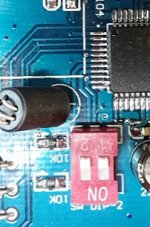
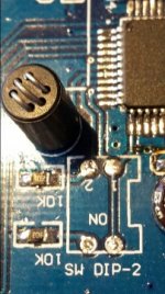
Hi,like most owner of this Weiliang (AK4495 + AK4118 V.1.1) board, I was wondering what those dip switches function was. As it was difficult to follow the tracks on the PCB, I unsoldered the dip switch and discovered a design mistake: the PCB is designed to receive two jumpers, not a dual dip switch. If you look at the photos, you will notice that the right dip switch is short circuited by a track (which is tied to Vdd : High Level), you’ll also notice the two soldering hole of the left dip switch are both tied to resistors (pull down resistors) .That means the two dip switches are useless. The switches (or jumper) have to be installed first one: between hole identified 1 and 2, and second one: between the two other soldering hole.
According to AK4495 datasheet, on this board, the 4495 is running in parallel mode (pin 12 PSN is High) then the digital output filter configuration is determined by the pins 5 (SSLOW for Super Slow), 7 (SD for Short Delay) and 8 (SLOW). Pin 8 is tied to the soldering hole number 2, thus the jumper closest the 4495 is SLOW. Pin 7 is tied to the other jumper, wich is SD. Surprisingly pin 5 SSLOW is tied to Vdd (High) that means the filter is aimed at operating at slower sampling frequencies as described in page 28 of the datasheet which describe digital filter setup in parallel mode:
************
SD SLOW Mode
L L Sharp roll-off filter
L H Slow roll-off filter
H L Short delay Sharp roll-off filter (default)
H H Short delay Slow roll-off filter
The AK4495S/95 can be operated on a slower sampling frequency. This mode is available when the SSLOW pin = “H”.
*********************
This SSLOW mode is not described at all in the datasheet and all frequency graphs and filter response measurements graphs are made with SSLOW set to Low, not High. This raise two questions (is there any Asahi Kaisei engineer reading this posts?!) what’s the function of SSLOW and associated consequences on performance?, and why the designer of this board designer choose to use SSLOW mode ? What will I do soon: plug SD and SLOW to the Arduino I use on top of the board and maybe unsolder pin 5 in order to tie it to ground.
According the previous table the current and unmodifiable (without soldering iron) setup of the board AK4495 digital filter is: Sharp-roll filter with Super slow mode.
To end, most of the AK4495 board I’ve seen on ebay, aliexpress, etc (there’re many variants) have a very close PCB layout and I’ve always seen the dual red dipswitch close to the AK4495, the self, the pull down resistors,…Do they all share the same design flaw ?
Attachments

Mine has been supplied by the DAC board vendor, this his an seven pin one, available in many Internet shops for around 45$. It works, but some capacitors are not the right ones (electrolytic rather than low ESR according to the datasheets) and picking the right driver was difficult. Now, it works fine.
If this board is intended to be used with the 4495 DAC, you should notice that the Weilliang board AK44995+AK4118 V.1.1 doesn't support DSD. As said in my previous post the 4495 is operating in parallel control mode, this mode disable DSD support.
If this board is intended to be used with the 4495 DAC, you should notice that the Weilliang board AK44995+AK4118 V.1.1 doesn't support DSD. As said in my previous post the 4495 is operating in parallel control mode, this mode disable DSD support.
Mine has been supplied by the DAC board vendor, this his an seven pin one, available in many Internet shops for around 45$. It works, but some capacitors are not the right ones (electrolytic rather than low ESR according to the datasheets) and picking the right driver was difficult. Now, it works fine.
If this board is intended to be used with the 4495 DAC, you should notice that the Weilliang board AK44995+AK4118 V.1.1 doesn't support DSD. As said in my previous post the 4495 is operating in parallel control mode, this mode disable DSD support.
This message was an answer to the message #53 of skrstic...
AIM65,
I am thinking of buying this board, what is your opinion do you recommend it? Elaborate if you can.
Thanks.
I am thinking of buying this board, what is your opinion do you recommend it? Elaborate if you can.
Thanks.
This message was an answer to the message #53 of skrstic...
😕
On the way YJ 32BIT 384K SA9227 USB card for YJ all DAC Completed board-in Amplifier from Consumer Electronics on Aliexpress.com | Alibaba Group .
There is a dual AK4495S version on ebay which claimed as supporting dsd via external usb/i2s adapter. Has anyone noticed this board too?
- Home
- Source & Line
- Digital Line Level
- Finally Weiliang released ak4495+ak4118 dac today.