This sort of extreme high capacitance cable will make some amplifiers unstable and modify the frequency response of others
Do you have real world examples or is this mathematical/theoretical speculation? Unstable in what way? How did you isolate the wire as the instability? How much capacitance are we talking about? My real world experience leads me to believe that this is largely speculative refuse.
Your probably right Max:
1 - Before measuring the cable with my 10 cent, old, chinese meter I measured a 15 microfarads Mundorf and it measured 19, so I deducted my meter calibration.
2 - I took a few measurements of the ribbon, before posting, and it measured between 3.6 and 4 nf so taking into account point 1 it could really be around 3nf
3 - My Cat6a as =< 2 meters and it measures 420pf (foiled and shielded it's stable).
Now for the music... I'm burning in my latest build a bass reflex bookshelf with Markaudio Alpair 7p that are known, in this and other forums, for having a harshness in the high frequencies during their early life, now, with the new cables, my subjective opinion, is that they sound better across the all range and the violins are clearly less harsh, is this only due just to the drivers settling in, or are the cables helping?
Will have a more concrete opinion in some weeks...
In the case of the cat6a cables I'm using they are S/FTP and the magnetic coupling between pairs is prevented by the individual foil around each pair, so they can have the same twist rate.
Foil cannot prevent magnetic coupling between the pairs. It can fight electric coupling however.
This article, paragraph 6..
Difference between Cat 5e and Cat 6a cable
Quote:
""When a cable contains a small number of pairs having the same twist rate, common-mode rejection is less effective because the conductors do not twist relative to one another. To mitigate this effect, adjacent pairs are manufactured with slightly different twist rates. ""
As to twist rate, this link shows pictures of the cable types and discusses the twist pitch differences.
What Kind of Ethernet (Cat5, Cat5e, Cat6, Cat6a) Cable Should I Use?
Quote: ""Cable twisting length is not standardized, but typically there are 1.5-2 twists per cm in Cat-5(e) and 2+ twists per cm in Cat-6. Within a single cable, each colored pair will also have different twist lengths based on prime numbers so that no two twists ever align. The amount of twists per pair is usually unique for each cable manufacturer. ""
John
Do you have real world examples or is this mathematical/theoretical speculation? Unstable in what way? How did you isolate the wire as the instability? How much capacitance are we talking about? My real world experience leads me to believe that this is largely speculative refuse.
Davidsrsb is quite correct.
The problem is the amplifier's open loop gain at very high frequencies. If the amplifier has very high bandwidth, a capacitive load can cause the phase margin to decrease below zero. Sufficient capacitance, the amplifier will oscillate at a very high frequency if the resistive component of the end load becomes too high, leaving the capacitance by itself.
Historically, this was found out when some amps blew up as a result of very low inductance cables.
jn
The problem is the amplifier's open loop gain at very high frequencies. If the amplifier has very high bandwidth, a capacitive load can cause the phase margin to decrease below zero. Sufficient capacitance, the amplifier will oscillate at a very high frequency if the resistive component of the end load becomes too high, leaving the capacitance by itself.
Historically, this was found out when some amps blew up as a result of very low inductance cables
I understand, that’s why I said largely and asked for real world examples, what capacitance etc...just because it’s possible to create a condition does not mean it’s real world issue. I am sure it’s historical happened and technically possible but would the historicity conditions desist today? Do you know anyone who has accidentally produced this issue with a modern amplifier and high capacitance cable? I have done many installs and know a few folks and I have not seen this issues in 2020 in the real world
Last edited:
I've studied this things in my early twenties and have been forgetting for 40 years but if I remember correctly a foil can prevent magnetic field interference if both ends of the foil are grounded, for electric field interference only one end needs to be grounded.Foil cannot prevent magnetic coupling between the pairs. It can fight electric coupling however.
Jorge
I understand, that’s why I said largely and asked for real world examples, what capacitance etc...just because it’s possible to create a condition does not mean it’s real world issue. I am sure it’s historical happened and technically possible but would the historicity conditions desist today? Do you know anyone who has accidentally produced this issue with a modern amplifier and high capacitance cable? I have done many installs and know a few folks and I have not seen this issues in 2020 in the real world
You asked:""Do you have real world examples or is this mathematical/theoretical speculation? Unstable in what way?""
So my answer was that it was real world, and absolutely supported by math and design criteria/standards. Amplifiers in general are not made with such high bandwidths, one reason is to prevent any load/cable instabilities.. And I answered your "in what way" question as oscillation due to loss of phase margin.
I have worked with audio since I was avoiding velociraptors, and I too have never had the problem.
I am also confident you do not use very low inductance cables in any of your installs, probably just normal #10, #12 or #14 twisted for speakers. So I wouldn't expect many to have seen this problem nowadays.
But some high end, custom, diy, amps may not have been designed with this in mind.
jn
Second part is correct. That said, it can be very challenging to fight EMI, especially if you have more than one shielded cable going to the same equipment. Many apps have double shielded, where one shield goes to both grounds, the other is connected at one end. It's great until you connect the second cable, then neither fully connected shield works properly.I've studied this things in my early twenties and have been forgetting for 40 years but if I remember correctly a foil can prevent magnetic field interference if both ends of the foil are grounded, for electric field interference only one end needs to be grounded.
Jorge
Foil is generally of insufficient conductivity to fight magnetic intrusion by generation of currents. So, no, the foil cannot work better at magnetic interference if both ends are grounded.
In essence, the twist is the key to cancellation of magnetic interference. And the different twists in cat cable is part of that.
jn
This is an interesting thread about the capacitance/inductance of cables.
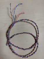
I did a braided speaker cable from a cheap multistrand wire Cat 6 cable. The cables are about 4 meters long and used for the speakers in my study. I use them mainly for background music when I work, so no real reason to turn up the volume.
The picture is from a short cable I'm will use to try out between my volume control and power amp.
I have no idea what the impedance of that cable is going to be. Anyone?
Attachments
Last edited:
The impedance will be that of a single pair divided by the numbers of pairs.
If the pair is 100 ohms, 4 in parallel will give 25 ohms.
But only if you connect all whites together, and all colors together.
I had a tech make a 15 foot run with 6 cat5e cables paralleled, 24 pair. It gave me very close to 4 ohms, I used it to do a ten microsecond risetime 40 volt pulses into a 4 ohm serpentine stainless steel resistor immersed in liquid helium, the waveform was perfect, no reflections.
For speaker runs, I would never recommend more than 4 pairs if you want to play.
jn
Last edited:
But some high end, custom, diy, amps may not have been designed with this in mind.
I think you proved my point when you said you had plenty of experience and have never seen it. I have a kenwood m1 with response to 300k and the ability to extend feedback to the speakers, do you think this would make a fair modern test bed? What do you think the maximum capacitance you could practically produce with speaker wire?
So it is a fake cable. Ethernet cable has always had different twist rates as part of the spec. This means any parameters are suspectAbout the cat6a cable it's 4 pairs of 0,56 mm, picture attached, I've been using it because it as the same twist rate in all the pairs (I've dismantled same cat cables that, if I remember, had a > 5% difference in length between pairs) and it should be able to handle my 2x40W amp.
The new one should handle about 2.5X the power.
Here is the fake data to the fake cable.So it is a fake cable. Ethernet cable has always had different twist rates as part of the spec. This means any parameters are suspect
Here is a article about the fake magnetic shielding with foil
Here is the fake data to the fake cable.
I did not see any mention of twist pitch specification, so cannot say if it is a fake or not. However, davidrsb is correct that the four pairs by spec, must have twist pitches that are not integral ratios.
Here is a article about the fake magnetic shielding with foil
Actually, re-read the second paragraph and consider what I earlier said about the conductivity of the foil.
Quote:""For low frequencies an overall screen, grounded only at one end, provides good shielding from capacitively coupled interference but none at all from the magnetic fields, because this can only occur if current flows in the screen. To shield against a magnetic field, both ends of the screen must be grounded. This allows an induced current (IS) to flow in the screen which will oppose the current induced in the centre conductor. ''
Bold/italic by me..
They talk about a screen that can carry current. A foil is not conductive enough to do that, but a braid copper certainly is.
The beauty of a coaxial screen is, any current that flows through the braid will produce a magnetic field outside of the braid, but it produces no magnetic field inside the braid. An external magnetic field caused by screen current will be 180 degrees out of phase from the inducing time varying magnetic field, so the net flux the inner conductors see is reduced by screen current.
IEEE-STD-1050 had some good dialogue on this, too bad it was retired.
jn
Last edited:
No, I simply stated that neither you nor I will ever use high capacitance speaker cables for an install, so neither of us will ever see it occur. Nor, would we choose a hot barely stable amplifier to drive an esoteric very expensive speaker cable in an install that we would have to come back and fix when it went belly up.I think you proved my point when you said you had plenty of experience and have never seen it.
I've made cables with 10 nH per foot, so they ran about 330 pf per foot. a 15 foot length, 5000 pf. The 4 ohm cable I made, probably 7000-8000 pf.I have a kenwood m1 with response to 300k and the ability to extend feedback to the speakers, do you think this would make a fair modern test bed? What do you think the maximum capacitance you could practically produce with speaker wire?
Honestly, I would probably approach a test of that type by starting low pf, and testing the amp step response no load just capacitance, then keep raising the capacitance until it starts to show issues. Doing a single high C test might not end up well. Going up slowly at least gives you the possibility of seeing where the amp starts to approach instability, hopefully without releasing the magic smoke.
ps...I mention using no load, just capacitance, as the second thing that has to happen is that the speaker unloads at frequency, meaning that the only energy storage mechanism is the capacitance of the cable. That is also why I mentioned a Zobel at the cable z, as that provides the needed load for the amp/cable when the speaker doesn't draw current.
jn
Last edited:
At least it has much more cooling surface, so it definitely must handle more power. 🙂The new one should handle about 2.5X the power.
That is so for Cat.5 cables. Cat.6 have a little other design so may differ (I don't know for sure about Cat.6).So it is a fake cable. Ethernet cable has always had different twist rates as part of the spec.
I think your right the difference in length between the ethernet cable pairs (delay skew) should be smaller for backbone cables than for patch cables (same delay skew allowed for bigger lengths) also with greater speeds and the use of all the cables for data transmission it makes sense to me to have smaller delay skews (don't know what the regulation says).That is so for Cat.5 cables. Cat.6 have a little other design so may differ (I don't know for sure about Cat.6).
One of the major reasons for the RIP for parallel data transmission in computers is the smaller delay skews needed with the increasing speeds.
- Home
- Design & Build
- Parts
- Finally replacing my budget Cat6 speaker cables...