Hello all!
Is there a difference between the feedback in this amplifier made with resistors: [(200k/10k) +1, and [(20k/1k) +1], if there is in what?
If measurements can?
thank you
Is there a difference between the feedback in this amplifier made with resistors: [(200k/10k) +1, and [(20k/1k) +1], if there is in what?
If measurements can?
thank you
The higher values will lead to more Johnson noise. Whether that becomes audible depends on the rest of your system, especially on the sensitivity of your speakers.
You will notice a difference in DC offset.
Depending on the parasitic capacitance of the PCB, higher values resistors can lead to different amp behaviour at high frequencies and can make it necessary to use a compensation capacitor, when you wouldn't need one with lower resistor values for the same gain.
You wouldn't want the feedback resistor higher than 115k. I doubt if you'd actually want it that high, but 200k is not especially valid nor desirable for LM1875 non-inverting amplifier.
High values of NFB resistors allow lower values of DC blocking capacitors.
This can be a very good compromise if you want to adopt AC coupled amplifier with wide audio bandwidth and do not want to use any polarised nor electrolytic capacitors.
If the Power amp gain is relatively low then 200k for both Rin and NFB upper leg resistor will not create much additional noise.
If you use Cherry's suggested NFB, the Rin resistor can be 3 times the NFB upper leg resistor and still maintain DC balance of LTP currents/voltages.
From BrianGT in 11th post -"Wire one of the GND connections on the PSU board to the chassis ground."
Would any of the 4 holes marked pg+ or pg- be the ones? And share it with a wire that goes to the amp board? There is no chassis yet. Where would the chassis gound be made?
Would any of the 4 holes marked pg+ or pg- be the ones? And share it with a wire that goes to the amp board? There is no chassis yet. Where would the chassis gound be made?
High values of NFB resistors allow lower values of DC blocking capacitors.
This can be a very good compromise if you want to adopt AC coupled amplifier with wide audio bandwidth and do not want to use any polarised nor electrolytic capacitors.
If the Power amp gain is relatively low then 200k for both Rin and NFB upper leg resistor will not create much additional noise.
If you use Cherry's suggested NFB, the Rin resistor can be 3 times the NFB upper leg resistor and still maintain DC balance of LTP currents/voltages.
I can't get that to work right. The soundfield collapses down to a tiny size and the output is somewhat raspy/analytical. This sound happens when its run out of speed. The highest figures I can get you is 115k with 3.9k divider for gain. That works okay. You could go higher if lower gain, but a computer source or mp3 player might start internal clipping if amp gain is too low.
But the good news is that this 3.9k is within range to use a 100uF cap for NFB cap, and the great news is that it is very easy to find excellent quality 100uF (and smaller) caps. This can be paralleled with a really tiny value polyester dip cap for excellent results since the frequency response will stay level. At this point, NFB cap selection gets extremely easy.
Do you mind posting a sketch involving the Rin resistor value relating to your comment about Dr. Cherry's NFB tapping? If I remember correctly, the speaker zobel resistor has to be a 3w or better model so as to avoid accidentally releasing the feedback loop upon resistor failure. Probably a less expensive resistor could be used if speaker zobel cap is 22nF. Its still enough to block some RF, but the smaller value cap removes some risk, and nobody would ever have an excuse to remove the zobel for audio purposes since that is so very far above the audio band. 🙂
Last edited:
I've sent BrianGT this question via email along with some other kit-related questions, but this should be super-simple to answer here. For the kits purchased from chipamp.com -- are the LM1875T chips meant to be included in the kit, or not? The kit I received included everything but these chips and I was trying to figure out if the omission was intentional or not.
Holy smokes, talk about customer service. Posted here just wanting a quick answer before I sent in my DigiKey order, but seems even that was unwarranted; just got tracking info via email informing me that the missing bits are on their way!I've sent BrianGT this question via email along with some other kit-related questions, but this should be super-simple to answer here. For the kits purchased from chipamp.com -- are the LM1875T chips meant to be included in the kit, or not? The kit I received included everything but these chips and I was trying to figure out if the omission was intentional or not.
 Thanks Brian! Can't wait to start building this thing.
Would it be possible to replace the 22k resistors on BrianGT's amp boards with 1/4 watt instead of 1/2 watt. Having a hard time sourcing 1/2 watts that small in Canada. Thanks for your help.. JohnnyP
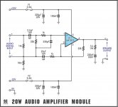
Audio Amplifier with LM1875
Hi all!
Here are two seeds on the internet where different feedback: Av=(22k/1k)+1 and Av=(180k/10k)+1 !?
Which schematic better?
And here's how I made audio amplifier with the LM1875 .
thank you!
Hi all!
Here are two seeds on the internet where different feedback: Av=(22k/1k)+1 and Av=(180k/10k)+1 !?
Which schematic better?
And here's how I made audio amplifier with the LM1875 .
thank you!
Attachments
Last edited:
JohnnyPOO, Please take a look at this thread. A new approach.
http://www.diyaudio.com/forums/chip...bolck-briangt-lm3886-upgrade.html#post2924833
http://www.diyaudio.com/forums/chip...bolck-briangt-lm3886-upgrade.html#post2924833
There is much to commend post151 schematic.
It shows:
Input filters
AC coupled.
Local decoupling
Output Zobel
Fused supply rails
Separate Signal and Power Grounds.
All that's left is ON/OFF muting and selecting component values.
It shows:
Input filters
AC coupled.
Local decoupling
Output Zobel
Fused supply rails
Separate Signal and Power Grounds.
All that's left is ON/OFF muting and selecting component values.
Would it be possible to replace the 22k resistors on BrianGT's amp boards with 1/4 watt instead of 1/2 watt. Having a hard time sourcing 1/2 watts that small in Canada. Thanks for your help.. JohnnyP
That is a low current area and thus 1/4w will do fine.
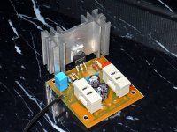
I haven't had a chance to work on the manual yet, but here are some board pictures, and info:
Amp board:
An externally hosted image should be here but it was not working when we last tested it.An externally hosted image should be here but it was not working when we last tested it.
R1 - not used (optional resistor to ground before C1)
R2 - 22k (input to ground resistor)
R3 - 1k (gain resistor , gain = 1 + R4/R
R4 - 22k (nfb resistor - on bottom of pcb)
R5 - 2.7 2w (optional - zobel network)
R6 - jumper (optional resistor between input ground and output ground)
C1 - 2.2µF (optional input capacitor)
C2 - 22µF bipolar (optional)
C3 - 0.1µF (power supply decoupling)
C4 - 0.1µF (power supply decoupling)
C5 - 0.1µF (power supply decoupling)
C6 - 47µF (power supply decoupling)
C7 - 0.1µF (optional - zobel network)
PSU board:
An externally hosted image should be here but it was not working when we last tested it.An externally hosted image should be here but it was not working when we last tested it.
R0 - 10k (series resistor for LED)
R1,R2 - 1 2w (optional "snubber" network capacitors)
C1,C2 - 1500µF (main power supply caps)
C3,C4 - 0.1µf (power supply decoupling)
C5,C6 - 0.1µf (optional "snubber" network capacitors)
D0 - blue LED
D1-D4 - MUR860
Transformer wiring:
For the PSU transformer connections, AC1 denotes the first secondary winding of the transformer, and AC2 denotes the second secondary winding of the transformer. It is also possible to use a center tapped transformer with this PSU board by wiring the center-tap to either AC1(bar over top) or AC2.
Size:
As for size, the LM1875 amp boards are almost half the size of the original LM3875/LM3886 amp boards.
Basic Assembly Info:
Solder components on board in order from lowest profile to highest profile, with the PSU diodes and LM1875 chip being soldered last.
As the pics show, the boards were made on the 11th week of 2007... over a year ago. I believe I mailed 10-15 boards out to various people, so let me know if you have any additional questions,
Thanks to Allan for transcribing his component notes and taking pictures!
--
Brian
Does anyone have the original pictures for this? Was a guide ver made?
Brian's kit is here: LM1875 Amplifier Kit | Chipamp.comDoes anyone have the original pictures for this? Was a guide ver made?
It seems that there's no published manual nor pictures on the site at this time. That site needs some maintenance. However, the boards may still be available.
I just discovered these chipamps because of my dedication to the great sound of the Renkforde E-SA9 amp.
It had a lot of distorsion but it sounded great and i found out that the distorsion came from the JRC 4558 chips that took care for the bass and treble adjustment.
Now i am left with the great sounding LM1875, thats the reason it sounded great.
I will rebuild this amp in a chipamp in this way and i asked myself the last days what the best parts are to use.
I came with Elna Simic 2 caps for the PSU, (those might be better than the Panasonic caps) and also this type for all other other electrolitics.
In the signal path i will use Caddock MP resistors.
Also i will use Evox Rifa MMK5 capacitors voor coupling, the 2.2 uF.
Also a ALPS potentiometer of cause.
Are there any other advices in what type components to use ?
And i ask muself why the power capacitors are only 1400uF, why not bigger ?
In the original Renkforce E-SA9 its 3300uF.
Hello Thed,
Have a look at Mick Feuerbacher Audio Projects Mick Feuerbacher's site. If you want an austere (and to my mind rather thin and weedy) amp make his 'Copper' one, if you want one with a big fat warm sound build one with a snubberized PSU. They are both on there.
Cheers - Jim
Have a look at Mick Feuerbacher Audio Projects Mick Feuerbacher's site. If you want an austere (and to my mind rather thin and weedy) amp make his 'Copper' one, if you want one with a big fat warm sound build one with a snubberized PSU. They are both on there.
Cheers - Jim
MMM, Sounds like mono blocks.
Snubberrrrrrrrr.
Is it mentally ?
All the discussions about best sounding components will be like this.
Just good schielding i would say in a enclosesure.
I will snubber !
Is there no good power regulator that wil go to 18 volts ?
So stupid..., i will go in a humm any minute now.
But there is !!! but no one found above 48volts if i am correct.
For other aplications you could them connect them in series like batteries.
Last edited:
If the surfaces are "hard" then compound must be used eg. mica, metal, Kapton etc.
If one of the surfaces is "soft" then the insulator itself fills all the gaps thereby eliminating the air.
if metal is used would conduct, original question is applying heat sink without conducting electricity but with conduction of heat...
- Status
- Not open for further replies.
- Home
- Amplifiers
- Chip Amps
- Finally made a LM1875 amp