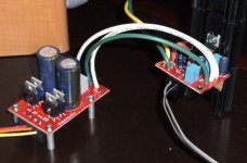
After having a stack of boards sitting around for a year, my friend Allan convinced me to help him make an amp with them. We put a stereo amp together with them last night. I am quite pleased at how the boards work together.
Now it is time to put together a nice compact chassis for it. We used a small Avel Lindberg 2x18vac transformer.
Here is a pic:
Now it is time to put together a nice compact chassis for it. We used a small Avel Lindberg 2x18vac transformer.
Here is a pic:
Attachments
Stuffing guide?
Brian,
I have been in the same mode with the boards I got from you.
Would you mind posting a stuffing guide?
Everytime I looked at them I got myself confused!
Thanks,
Rick McInnis
Brian,
I have been in the same mode with the boards I got from you.
Would you mind posting a stuffing guide?
Everytime I looked at them I got myself confused!
Thanks,
Rick McInnis
Rick,
I(Allan) am currently working on that supply list for you, as well as a manual that is thorough yet not too confusing to a novice DIYer such as myself.
In the meantime, Brian and I can answer questions you might have to help you put those boards to use.
I(Allan) am currently working on that supply list for you, as well as a manual that is thorough yet not too confusing to a novice DIYer such as myself.
In the meantime, Brian and I can answer questions you might have to help you put those boards to use.
Happy to see this. More efforts to be newbee friendly.
You reap what you sow - it will come back to you in spades.
Bluto
You reap what you sow - it will come back to you in spades.
Bluto
Alan,
Thanks in advance!
I have built numerous of Peter Daniel's 3875 amps, which are self explanatory.
There seem to be places for additional components that confuse me as to where to put the "important" ones.
My intention was to uset the same values/components as recommended by Mr. Daniel so I can get a true idea of the differences between the chips.
I look forward to seeing the "stuffing guides" becoming availabe. Thanks again,
Rick McInnis
An observation:
I've noticed something about the LM1875 and its power supply.
Mine likes several of 2200uF per rail much better than any amount of larger caps. There's a difference to the speed and impact of the bass notes. This "impact" is helpful.
At onboard with the amplifier, it doesn't matter so much, except that the sound is clearest with one of these: 220uF, 330uF, 470uF. And, when the sound was clearest by this selection, heat is lowest.
This arrangement allowed for 30v rails and running cool; however, it was past the amperage limiter when used along with 4 ohm speakers. Generally, the 26v rails worked for most speakers. On the 30v rails, use with 8 ohm speakers is quite exciting.
For the rectifier, it matters not whether its botique or a simple arrangement. A nice, trouble-free KCPU1004 (KBU 10a 400w) one-piece rectifier is brilliantly arranged so that its + and - can correspond to the traces on a PCB, lining up nicely with the capacitors. This performer also makes hookup to be nicely simplified.
A little helper: At the power supply board, one of the power caps (per each rail) can be bypassed with 47nF or 68nF. This has been observed to lend a bit more speed to the bass notes.
Well, that was my observation for today. 😉
I haven't had a chance to work on the manual yet, but here are some board pictures, and info:
Amp board:
R1 - not used (optional resistor to ground before C1)
R2 - 22k (input to ground resistor)
R3 - 1k (gain resistor , gain = 1 + R4/R
R4 - 22k (nfb resistor - on bottom of pcb)
R5 - 2.7 2w (optional - zobel network)
R6 - jumper (optional resistor between input ground and output ground)
C1 - 2.2µF (optional input capacitor)
C2 - 22µF bipolar (optional)
C3 - 0.1µF (power supply decoupling)
C4 - 0.1µF (power supply decoupling)
C5 - 0.1µF (power supply decoupling)
C6 - 47µF (power supply decoupling)
C7 - 0.1µF (optional - zobel network)
PSU board:
R0 - 10k (series resistor for LED)
R1,R2 - 1 2w (optional "snubber" network capacitors)
C1,C2 - 1500µF (main power supply caps)
C3,C4 - 0.1µf (power supply decoupling)
C5,C6 - 0.1µf (optional "snubber" network capacitors)
D0 - blue LED
D1-D4 - MUR860
Transformer wiring:
For the PSU transformer connections, AC1 denotes the first secondary winding of the transformer, and AC2 denotes the second secondary winding of the transformer. It is also possible to use a center tapped transformer with this PSU board by wiring the center-tap to either AC1(bar over top) or AC2.
Size:
As for size, the LM1875 amp boards are almost half the size of the original LM3875/LM3886 amp boards.
Basic Assembly Info:
Solder components on board in order from lowest profile to highest profile, with the PSU diodes and LM1875 chip being soldered last.
As the pics show, the boards were made on the 11th week of 2007... over a year ago. I believe I mailed 10-15 boards out to various people, so let me know if you have any additional questions,
Thanks to Allan for transcribing his component notes and taking pictures!
--
Brian
Amp board:
An externally hosted image should be here but it was not working when we last tested it.
An externally hosted image should be here but it was not working when we last tested it.
R1 - not used (optional resistor to ground before C1)
R2 - 22k (input to ground resistor)
R3 - 1k (gain resistor , gain = 1 + R4/R
R4 - 22k (nfb resistor - on bottom of pcb)
R5 - 2.7 2w (optional - zobel network)
R6 - jumper (optional resistor between input ground and output ground)
C1 - 2.2µF (optional input capacitor)
C2 - 22µF bipolar (optional)
C3 - 0.1µF (power supply decoupling)
C4 - 0.1µF (power supply decoupling)
C5 - 0.1µF (power supply decoupling)
C6 - 47µF (power supply decoupling)
C7 - 0.1µF (optional - zobel network)
PSU board:
An externally hosted image should be here but it was not working when we last tested it.
An externally hosted image should be here but it was not working when we last tested it.
R0 - 10k (series resistor for LED)
R1,R2 - 1 2w (optional "snubber" network capacitors)
C1,C2 - 1500µF (main power supply caps)
C3,C4 - 0.1µf (power supply decoupling)
C5,C6 - 0.1µf (optional "snubber" network capacitors)
D0 - blue LED
D1-D4 - MUR860
Transformer wiring:
For the PSU transformer connections, AC1 denotes the first secondary winding of the transformer, and AC2 denotes the second secondary winding of the transformer. It is also possible to use a center tapped transformer with this PSU board by wiring the center-tap to either AC1(bar over top) or AC2.
Size:
As for size, the LM1875 amp boards are almost half the size of the original LM3875/LM3886 amp boards.
Basic Assembly Info:
Solder components on board in order from lowest profile to highest profile, with the PSU diodes and LM1875 chip being soldered last.
As the pics show, the boards were made on the 11th week of 2007... over a year ago. I believe I mailed 10-15 boards out to various people, so let me know if you have any additional questions,
Thanks to Allan for transcribing his component notes and taking pictures!
--
Brian
As for the wiring connections:
Amp board:
V+ = goes to the V+ connection on PSU board
V- = goes to the V- connection on PSU board
GND = goes to GND connection on PSU board
IN = goes to positive input signal
SG = goes to input ground (signal ground)
OUT = goes to positive output terminal
OG = goes to output ground
PSU board:
AC1 connections = goes to first secondary winding on transformer
AC2 connections = goes to second secondary winding on transformer
(for center-tapped tranformer, connect center-tap to either AC1(bar over top) or AC2 (no bar)
V+ = goes to V+ connections on amp boards
V- = goes to V- connections on amp boards
GND = goes to GND connections on amp boards, and also a connection to the central chassis ground
Other Connections:
For the input AC connections, put the AC H connection in series with a fuse (I used 2A slo blow), and in series with a power switch if desired. This will then wire into the first primary. Wire the AC N connection to the other primary wire. Wire the AC earth ground connection to the main chassis ground.
Variations:
-One could decide to remotely wire the D0 power supply LED to the front panel for indicating the the amp is on.
-One could decide to route the output ground to the central ground, instead of the OG connection on the PCB.
-If PSU cap bleeder resistors are desired, solder them to the underside of the pcb on the 1500uF capacitor terminals. I used 2.2k 2w resistors for this purpose on the initial test amp.
Transformer selection:
I used a 160va 2x18vac Avel Lindberg transformer from Parts Express, and anything similar should work. The acceptable power supply range from V+ to V- is 16-60v. See the datasheet for power output levels with various supply voltage
Datasheet from National:
http://www.national.com/mpf/LM/LM1875.html
(the schematic in manual is very close to the actual circuit used on the amplifier PCB)
--
Brian
Testing Procedure once boards are assembled:
-first, make sure to wire up the fuse and AC terminals correctly. Test with a multimeter set on ACV to make sure that your switch works. Wire from the AC H terminal on the AC socket to a fuse holder, and then into a switch.
-connect the first wire of the transformer primary to the AC H connection on the power switch
-connect the second wire of the transformer primary to the AC N connection on the ac input terminal.
-connect the earth ground from the ac inlet to the main chassis ground
-for US or other 120v countries, if your transformer has dual primaries and is specified for either 115vac or 230vac, such as the Avel Lindberg common transformers, wire both the pairs of primary parallel with each other.
Here is a picture of the Avel Lindberg transformer wiring:
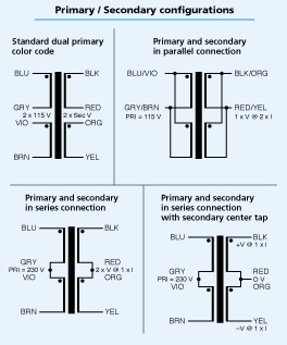
-For the Avel Lindberg transformer in the US, connect the Blue and Violet wires to the AC H connection on the switch, and the Gray and Brown wires to the AC N connection on the AC input terminal. For 230vac, connect the transformer primaries in series, as shown in the above image.
-Make sure to isolate the secondary wires from the transformer, and power up the amp to verify the voltages from the transformer secondary windings. If you have a 2x18vac transformer, you should now measure 18vac across each secondary (secondary 1 = black/red and secondary 2 = Orange/Yellow)
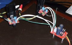
-power off the amp, and wire the secondary windings from the transformer into the AC1 and AC2 terminals on the power supply board. Here is a picture:
(AC1 = black, AC1(bar) = red, AC2 = orange, AC2(bar) = yellow)
-Wire one of the GND connections on the PSU board to the chassis ground.
-Once the transformer secondaries are connected to the PSU board along with the chassis ground connection, power up the amp to check the output DC voltages. Measuring from GND to V+ and from V- to GND should show ~25vdc if you are using a 2x18vac transformer.
-The LED on the PSU board should also be lit up, if installed correctly.
-Once the power supply voltages are verified, power the amp down, and wire up one amplifier board to the V+, V- and GND connections from the PSU board to the amp board.
-power up the amp again, and check the DC offset of the amplifier with the multimeter, by setting it to the minimum DC voltage setting, and measuring from OUT to OG. You should measure between 10-30mV, but under 100mV is acceptable.
-if all checks out, power down amp, and hook up the other channel and test it.
-once both channels are verified, connect the RCA input terminals to the IN and SG connections on the amp boards for both channels. Also connect the OUT and OG connections on the amp boards to the output terminals on the chassis.
-power the amp up again, and test the amp with a test speaker for both channels.
-Once all is verified, connect to your system and enjoy!
(note, this is a quick rough draft of the manual, and I will work this into a manual for putting together an LM1875. Let me know if you spot any issues, or have any comments)
--
Brian
-first, make sure to wire up the fuse and AC terminals correctly. Test with a multimeter set on ACV to make sure that your switch works. Wire from the AC H terminal on the AC socket to a fuse holder, and then into a switch.
-connect the first wire of the transformer primary to the AC H connection on the power switch
-connect the second wire of the transformer primary to the AC N connection on the ac input terminal.
-connect the earth ground from the ac inlet to the main chassis ground
-for US or other 120v countries, if your transformer has dual primaries and is specified for either 115vac or 230vac, such as the Avel Lindberg common transformers, wire both the pairs of primary parallel with each other.
Here is a picture of the Avel Lindberg transformer wiring:
-For the Avel Lindberg transformer in the US, connect the Blue and Violet wires to the AC H connection on the switch, and the Gray and Brown wires to the AC N connection on the AC input terminal. For 230vac, connect the transformer primaries in series, as shown in the above image.
-Make sure to isolate the secondary wires from the transformer, and power up the amp to verify the voltages from the transformer secondary windings. If you have a 2x18vac transformer, you should now measure 18vac across each secondary (secondary 1 = black/red and secondary 2 = Orange/Yellow)
-power off the amp, and wire the secondary windings from the transformer into the AC1 and AC2 terminals on the power supply board. Here is a picture:
An externally hosted image should be here but it was not working when we last tested it.
(AC1 = black, AC1(bar) = red, AC2 = orange, AC2(bar) = yellow)
-Wire one of the GND connections on the PSU board to the chassis ground.
-Once the transformer secondaries are connected to the PSU board along with the chassis ground connection, power up the amp to check the output DC voltages. Measuring from GND to V+ and from V- to GND should show ~25vdc if you are using a 2x18vac transformer.
-The LED on the PSU board should also be lit up, if installed correctly.
-Once the power supply voltages are verified, power the amp down, and wire up one amplifier board to the V+, V- and GND connections from the PSU board to the amp board.
-power up the amp again, and check the DC offset of the amplifier with the multimeter, by setting it to the minimum DC voltage setting, and measuring from OUT to OG. You should measure between 10-30mV, but under 100mV is acceptable.
-if all checks out, power down amp, and hook up the other channel and test it.
-once both channels are verified, connect the RCA input terminals to the IN and SG connections on the amp boards for both channels. Also connect the OUT and OG connections on the amp boards to the output terminals on the chassis.
-power the amp up again, and test the amp with a test speaker for both channels.
-Once all is verified, connect to your system and enjoy!
(note, this is a quick rough draft of the manual, and I will work this into a manual for putting together an LM1875. Let me know if you spot any issues, or have any comments)
--
Brian
Here is a picture of the wired up amplifier board:
Note: I would highly recommend using different colors for V+ and V-. For this amp, the wiring as done with what I had on hand, and will be rewired for the final chassis setup.
I also installed output terminals for the output connections under the pcb, so that I could wire the test speakers directly into the PCB. For the final chassis wriing, the wires going to the output terminals will be wired directly to the PCB.
For heatsinks, I tested with the small heatsinks that I had on hand. With a single heatsink per channel, they got quite hot, so I connected 3 together to obtain a reasonable temperature for the heatsinks. We were able to run the amplifier at full power, and easily overwhelm the test speakers. At full power, the heatsinks were a bit warm, but not to hot to touch.
Note: make sure to insulate the heatsink from the LM1875 package, as it is not insulated like the LM3886TF chips.
--
Brian
An externally hosted image should be here but it was not working when we last tested it.
Note: I would highly recommend using different colors for V+ and V-. For this amp, the wiring as done with what I had on hand, and will be rewired for the final chassis setup.
I also installed output terminals for the output connections under the pcb, so that I could wire the test speakers directly into the PCB. For the final chassis wriing, the wires going to the output terminals will be wired directly to the PCB.
For heatsinks, I tested with the small heatsinks that I had on hand. With a single heatsink per channel, they got quite hot, so I connected 3 together to obtain a reasonable temperature for the heatsinks. We were able to run the amplifier at full power, and easily overwhelm the test speakers. At full power, the heatsinks were a bit warm, but not to hot to touch.
Note: make sure to insulate the heatsink from the LM1875 package, as it is not insulated like the LM3886TF chips.
--
Brian
Brian,
Are you selling (or going to be selling) these on the chipamp.com site?
I've been looking at trying out the lm1875 but haven't had the time or motivation to hardwire one together. A PCB would make things much easier.
Cool project.
Best,
KT
Are you selling (or going to be selling) these on the chipamp.com site?
I've been looking at trying out the lm1875 but haven't had the time or motivation to hardwire one together. A PCB would make things much easier.
Cool project.
Best,
KT
Brian we need to make a correction on that amp pcb part list. We are using the 47µF for c4 instead of the 0.1µF. I'm working on a manual for this project and it should be out soon. This is just something I noticed while doing a walkthrough.
zymurgn said:Brian we need to make a correction on that amp pcb part list. We are using the 47�F for c4 instead of the 0.1�F. I'm working on a manual for this project and it should be out soon. This is just something I noticed while doing a walkthrough.
Yeah, that was a typo that I made, thanks for catching it,
-Brian
Nice job Brian !
I'd like to buy some boards when available...
Some questions
PSU
Is one PSU board enough for two LM1875 modules ?
C1/C2 : I've got 1800µF/35v from Panansonic, does it fit ?
C3/C4/C5/C6 : 5mm footprint ?
R0 : 10k/.6W is Ok ?
AMP Boards
C2 : 3.5mm footprint ?
C3/C5 : 5mm footprint ?
C4/C6 : 2.5mm footprint ?
C7 : 5mm footprint ?
C1 : Philips MKT/250v is Ok ?
Many thanks 😉
160va 2x18vac Avel Lindberg transformer from Parts Express Part Number
Please post the Parts Express part number.
"......Transformer selection:
I used a 160va 2x18vac Avel Lindberg transformer from Parts Express, and anything similar should work. The acceptable power supply range from V+ to V- is 16-60v. See the datasheet for power output levels with various supply voltage......"
Thank You
Re: 160va 2x18vac Avel Lindberg transformer from Parts Express Part Number
http://www.partsexpress.com/pe/showdetl.cfm?&Partnumber=122-610
ppcblaster said:Please post the Parts Express part number.
"......Transformer selection:
I used a 160va 2x18vac Avel Lindberg transformer from Parts Express, and anything similar should work. The acceptable power supply range from V+ to V- is 16-60v. See the datasheet for power output levels with various supply voltage......"
Thank You
http://www.partsexpress.com/pe/showdetl.cfm?&Partnumber=122-610
- Status
- Not open for further replies.
- Home
- Amplifiers
- Chip Amps
- Finally made a LM1875 amp