So the chokes would go on the bottom line in the picture I posted and then go to ground after the last cap?
Also you wrote "Magnetic coupling into the output transformer from nearby power transformers, and ripple from the driver stage if not well filtered is more likely to dominate." So should I put a fariday cage type wall between the Pxt and Oxt?
A Faraday cage is effective against the E field (electrostatic coupling) and not effective against H field (magnetic coupling) Distance and orientation are your best friend here, and in terms of the driver just assuring that the ripple on the driver supply is reasonably low is sufficient. (A few mV)
And to your earlier question, yes ground is applied after the second choke in the ground side leg.
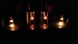
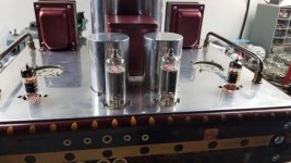
We moved in 2016 from Michigan to Albuquerque and the GM70 amp project has been in storage ever since. Now that I'm stuck at home I'm back on it. I wired up the filaments for the 6D22C rectifiers and 12GN7A driver tubes. Tomorrow I'll work on the GM70 heater power supply.