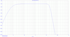
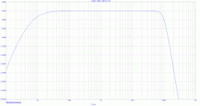
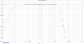
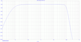
The frequency response looks decent. The 10 Ohm series resistor is need to limit current flowing throught the protection diodes.
Samuel
Samuel
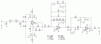
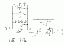
Attached is a revised version of the LNMP. I wanted to add the ability to vary the gain and also the high frequency bandwidth.
The AD797A provides 100x gain with the bandwidth set well beyond the desired frequency range. C8 and R7 form a high-pass filter with the -3 dB fc at about 7 Hz. The first half of the NE5532A provides additional gain that can be varied between 10x (providing an overall gain of 1000x) and 100x (providing an overall gain of 10,000x). Both NE5532A stages form a multiple feedback 3rd order Butterworth low-pass filter that allows the -3 dB fc to be changed between 20 kHz and 100 kHz. Frequency response results from a simulation of the entire circuit are attached.
Another possible configuration would involve setting the AD797A stage at 1000x and then vary the first half of the NE5532A between unity gain and 10x. Which configuration is preferable (e.g., from a noise perspective)?
Thanks,
Bryan
Attachments
Last edited:
Hi Bryan,
I would be interested to use such an amplifer as a front-end to a distortion measurement setup at low levels. That would be a reason to limit the gain of each individual stage to a value that would still give good linearity. Maybe not more than 100x, max.
My 2 eurocents.
jan didden
I would be interested to use such an amplifer as a front-end to a distortion measurement setup at low levels. That would be a reason to limit the gain of each individual stage to a value that would still give good linearity. Maybe not more than 100x, max.
My 2 eurocents.
jan didden
Last edited:
For lowest noise you want gain as early as poosible, i.e. 60 dB for the AD797. You may need to decompensate the AD797 though to get enough loop gain (see datasheet), and arrange a bias cancellation circuit for the noninverting input to get low offset.
Getting low distortion is quite a different task than just low noise; I'd build a separate preamp for this.
Samuel
Getting low distortion is quite a different task than just low noise; I'd build a separate preamp for this.
Samuel
[snip]Getting low distortion is quite a different task than just low noise; I'd build a separate preamp for this.
Samuel
Yes - I thought I could have my cake and eat it too .. 😉
jan didden
You may need to decompensate the AD797 though to get enough loop gain (see datasheet), and arrange a bias cancellation circuit for the noninverting input to get low offset.
Doesn't the AD797 include bias cancellation circuitry? Is it just that 1000x gain is too much for it to properly null the offset?
Thanks,
Bryan
Doesn't the AD797 include bias cancellation circuitry?
Yes, but apparently one that doesn't fully cancel input bias current (ask Scott Wurcer why this is how it is). 1.5 uA maximum is quite high; LT1028 does nearly 10x better than this.
Is it just that 1000x gain is too much for it to properly null the offset?
You do the math--how much offset related to the input causes 1.5 uA flowing through 1.5 kOhm? And how does this look at the output after 60 dB gain?
Of course the 1.5 uA is a worst-case figure; most parts will do much better. And the offset is low enough to not saturate the output straight away, but rather just eat a bit of headroom, which probably is acceptable for your application.
Samuel
1.5 uA maximum is quite high; LT1028 does nearly 10x better than this.
Hmm.... the LT1028 looks like a better part. Is there any reason why I couldn't use it (set to 1000x gain) in place of the AD797 in this circuit?
Although it seems like a non-inverting configuration is the way to go, LT uses the LT1028 in an inverting configuration in their LNA (see here: http://cds.linear.com/docs/Application Note/an83f.pdf). Any idea why?
Thanks,
Bryan
The LT1028 looks like a better part. Is there any reason why I couldn't use it (set to 1000x gain) in place of the AD797 in this circuit?
With a 75 MHz GBW product you get a 75 kHz BW at 60 dB noise gain. You can decompensate the AD797, which is not possible for the LT1028. A composite amplifier topology using another opamp would be suitable though.
LT uses the LT1028 in an inverting configuration.
Inverters are inherently well protected from input overloads.
Samuel
With a 75 MHz GBW product you get a 75 kHz BW at 60 dB noise gain. You can decompensate the AD797, which is not possible for the LT1028.
Yeah, just discovered that via simulation before I saw your post.
So getting back to the AD797 bias cancellation, the simulator indicates that the offset can be nulled by either: putting a ~36.5k resistor between the inverting input and the negative supply; or putting a ~5.5M resistor between the non-inverting input and the positive supply. Are either of these acceptable solutions?
Would an opamp-based DC servo be better from a noise perspective?
Thanks,
Bryan
Simulation is of little help for input bias cancellation; this is a very variable parameter--see the datasheet specs.
It probably was a bad idea from me to point this out. For a one-off build you can rely on the typical specs and just verify that opamp output offset is low enough. In mass production one might want to be a bit more prudent.
Samuel
It probably was a bad idea from me to point this out. For a one-off build you can rely on the typical specs and just verify that opamp output offset is low enough. In mass production one might want to be a bit more prudent.
Samuel
Attached is the revised filter for use with a 60dB first stage. I changed the ompamp to an OPA2211 since I had some around. It has less voltage noise and current noise than the NE5532A, but probably won't affect overall noise that much given that it's the final stage.
I haven't finalized the 60dB first stage. I'm considering a few hybrid (discrete/opamp) circuits, but each seems to involve a tradeoff of a few factors (noise, PSRR, operating voltage, etc.). It looks like it's time to start building...
I haven't finalized the 60dB first stage. I'm considering a few hybrid (discrete/opamp) circuits, but each seems to involve a tradeoff of a few factors (noise, PSRR, operating voltage, etc.). It looks like it's time to start building...
Attachments
you might want to look at http://focus.ti.com/lit/an/sboa015/sboa015.pdf and understand the fig 8/9 high gain composite amp compensations
I have used fig 9 comensation in strain gage amplifiers
trying to switch gain, bandwidth in the input amp where you are struggling to get the GBW needed to even begin with is trying to do too much
I would switch gain, bandwidth in the subsequent filters, not the the input where composite techniqes are needed for the GBW
Before proceeding with endless circuit iterations I think you'll need to define your needs. Previously you were aiming at < 1 nV/rtHz performance; now suddenly < 10 nV/rtHz seems enough, which is a rather trivial goal. It's difficult to give any advice without clear specs...
Samuel
Samuel
Previously you were aiming at < 1 nV/rtHz performance; now suddenly < 10 nV/rtHz seems enough, which is a rather trivial goal.
How did I indicate that less than 10 nV/rtHz is now enough?
-Bryan
How did I indicate that less than 10 nV/rtHz is now enough?
I deduced this from the latest schematic, where R1 = 1k limits performance to about 4 nV/rtHz. But from your question I take it that this was not intentional.
Samuel
I deduced this from the latest schematic, where R1 = 1k limits performance to about 4 nV/rtHz. But from your question I take it that this was not intentional.
Samuel
It's been ~1K all along. R1 in the latest schematic is R7 in post 42 and R6 in post 36. Why would the noise of this stage suddenly increase? Given that the gain is reduced (now 1X/10X from 10X/100X) and the value of the feedback resistors has decreased (highest value was 100K, now 10K), shouldn't the noise have decreased?
-Bryan
Your latest sch is just the filter/gain after the 1000x low noise stage?
for headroom I would consider "just" 100x front end gain - no explicit filter (decomp and 1st order filter feedback cap in 1st stage are incompatablie) and then you have 20 dB headroom for the next 2 amps/filters to knock down out of band noise
for headroom I would consider "just" 100x front end gain - no explicit filter (decomp and 1st order filter feedback cap in 1st stage are incompatablie) and then you have 20 dB headroom for the next 2 amps/filters to knock down out of band noise
Your latest sch is just the filter/gain after the 1000x low noise stage?
Correct.
for headroom I would consider "just" 100x front end gain - no explicit filter (decomp and 1st order filter feedback cap in 1st stage are incompatablie) and then you have 20 dB headroom for the next 2 amps/filters to knock down out of band noise
What do you mean by "20dB headroom to knock down out of band noise"? As an example, doesn't an active filter set at unity gain do just as good a job of attenuating out-of-band signals as an active filter with 20dB gain?
-Bryan
- Status
- Not open for further replies.
- Home
- Amplifiers
- Solid State
- Filters For Low-Noise Measurement Preamplifier
