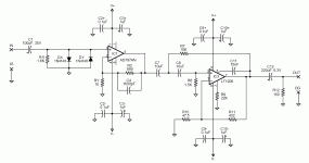
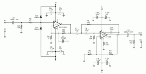
I've attached the revised schematic with clamping diodes.
Although I think the beginning of this article http://cds.linear.com/docs/Application Note/an83f.pdf describes it more eloquently than I can, I will try. Frequency range is ~10Hz to 100kHz. Noise level would be somewhere in the uV range on the low end, not sure about the high end. The LNMP would be driving an RMS voltmeter set to AC mode.
Regarding the input coupling cap, I presume I will have to go with some sort of electrolytic given the high capacitance. I've read that low-ESR caps are best here (e.g., Sanyo OSCON). However, the lowest ESR caps tend to not be offered above 20V or so, and I will definitely want to be able to measure PSUs with rails above 20V. So my question is how low of an ESR is needed? The Panasonic FC series or Nichicon UHE series will be around 120 mOhms, but this is quite a bit higher than the OSCONS which are in the 20-30 mOhm range.
Thanks,
Bryan
* in what frequency range you want to measure
* what the expected source noise level is
* how you want to measure noise (e.g. RMS level, FFT...)
Although I think the beginning of this article http://cds.linear.com/docs/Application Note/an83f.pdf describes it more eloquently than I can, I will try. Frequency range is ~10Hz to 100kHz. Noise level would be somewhere in the uV range on the low end, not sure about the high end. The LNMP would be driving an RMS voltmeter set to AC mode.
Regarding the input coupling cap, I presume I will have to go with some sort of electrolytic given the high capacitance. I've read that low-ESR caps are best here (e.g., Sanyo OSCON). However, the lowest ESR caps tend to not be offered above 20V or so, and I will definitely want to be able to measure PSUs with rails above 20V. So my question is how low of an ESR is needed? The Panasonic FC series or Nichicon UHE series will be around 120 mOhms, but this is quite a bit higher than the OSCONS which are in the 20-30 mOhm range.
Thanks,
Bryan
Attachments
I've attached the revised schematic with clamping diodes.
Although I think the beginning of this article http://cds.linear.com/docs/Application Note/an83f.pdf describes it more eloquently than I can, I will try. Frequency range is ~10Hz to 100kHz. Noise level would be somewhere in the uV range on the low end, not sure about the high end. The LNMP would be driving an RMS voltmeter set to AC mode.
Regarding the input coupling cap, I presume I will have to go with some sort of electrolytic given the high capacitance. I've read that low-ESR caps are best here (e.g., Sanyo OSCON). However, the lowest ESR caps tend to not be offered above 20V or so, and I will definitely want to be able to measure PSUs with rails above 20V. So my question is how low of an ESR is needed? The Panasonic FC series or Nichicon UHE series will be around 120 mOhms, but this is quite a bit higher than the OSCONS which are in the 20-30 mOhm range.
Thanks,
Bryan
Bryan,
How relevant is the input cap ESR in this app?
jd
Bryan,
How relevant is the input cap ESR in this app?
jd
From everything I've read, it seems that most prefer to use film caps in LNMP filter circuits. However, if electrolytics are used, most recommend caps with low-ESR.
-Bryan
I would say that the 1N4148's need some current limiting at the input... or even perhaps use a combination of R+1n4148+Zeners. Or clamp to the supplies.
Imagine connecting the input to say 50 volts DC...
Overvoltage Protection (OVP) for Sensitive Amplifier Applications - Maxim
Imagine connecting the input to say 50 volts DC...
Overvoltage Protection (OVP) for Sensitive Amplifier Applications - Maxim
The LNMP would be driving an RMS voltmeter set to AC mode.
And what AC meter do you use? What's it most sensitive range (i.e. how much gain do we need), what frequency range does it support (i.e. does it make sense at all trying to measure up to 100 kHz) and can it actually read true RMS on high crest factor signals?
So my question is how low of an ESR is needed?
So low that the ESR does not contribute any significant thermal noise--anything below 10 Ohm does well. In other words: *any* reasonable electrolytic cap you'll get your hands on.
What's actually more important is leake. Leakage current might contain noise which will flow through the 1k6 at low frequencies. I'd use a Panasonic FC or FM rated to at least 1.5x the maximum supply voltage you want to measure. If you want to measure both positive and negative supplies you can use a back-to-back series pair.
I would say that the 1N4148's need some current limiting at the input...
Sure--10 Ohms before them as mentioned in this thread above.
Or clamp to the supplies.
Again for sure--clamping to ground is not necessary.
Samuel
I'd have lots of comments to offer but you'd need to answer my questions first. If we don't know what you need we can't help.
Samuel
Samuel
And what AC meter do you use? What's it most sensitive range (i.e. how much gain do we need), what frequency range does it support (i.e. does it make sense at all trying to measure up to 100 kHz) and can it actually read true RMS on high crest factor signals?
I currently have a Fluke 189 that I plan to use to read the output from the LNMP. The specs seem to say that it will measure an AC signal up to 100kHz and down to 2.5 mv. See here: http://assets.fluke.com/datasheets/2153extspecs.pdf. It claims "true-RMS", but I doubt that it uses the thermal technique to make such measurements. I would guess that it uses the logarithmic method based upon the document here: http://cds.linear.com/docs/Application Note/an83f.pdf
Regards,
Bryan
Last edited:
So it looks like 60 dB gain is about right. I'd consider limiting the bandwidth to 20 kHz; this will reduce reading errors from the AC meter.
Now to the actual design: as mentioned before you should have a better low pass filter as this is far more important for the accuracy than the high-pass filter. Also you want 60 dB gain before the filter, otherwise it might contribute some noise. The LT1206 is definitely the wrong part here; you don't need its bandwidth, slew-rate or drive capability. So I'd suggest the following changes (assuming you stay with 100 kHz BW):
* Increase the bandwidth of the first stage to about 500 kHz; i.e. C4 = 330 pF.
* For stability reasons (see AD797 datasheet) you'll need a 100 Ohm resistor in series with C4.
* After the 40 dB stage use one section of a NE5532 to make a 20 dB inverting stage. The feedback network could use 1k/10k resistors. Add a 10 uF polyester cap in series with the 1k to set the high pass corner.
* Use the second half of the NE5532 to make a 3rd order Butterworth multiple feedback low pass filter which connects to the output of the 20 dB stage. One time constant of the overall 3rd oder filter is provided by the 20 dB stage (i.e. a cap in parallel with the 10k feedback resistor)--use one of the online calculators to derive the correct resistor/capacitor values.
* There is no need to AC couple the output of the preamplifier (i.e. skip C12 and R12) but you'll need a small resistor in series with the output to isolate capacitive loads.
* I'd avoid large power supply decoupling caps to ground. They will inject noise from the supplies into ground which might increase observed amplifier noise. Use two 100 nF to ground for the AD797 and a single 100 nF between the rails for the NE5532. Additionaly I'd use 10 Ohm resistors in series with the supply for the AD797 to dampen possible resonances on the supply rail. This should be enough to prevent stability issues.
That's about it for the moment, hope that makes sense.
Samuel
I will be point-to-point wiring this circuit and plan on mounting it in an all-metal box with 50-Ohm BNCs for input and output. Where should the box be connected to ground? I was thinking that I could use non-isolated BNCs and/or connect the ground of the circuit to say the bottom of the box...
How small of a resistor? 10R? 100R?
Thanks,
Bryan
* There is no need to AC couple the output of the preamplifier (i.e. skip C12 and R12) but you'll need a small resistor in series with the output to isolate capacitive loads.
How small of a resistor? 10R? 100R?
Thanks,
Bryan
* After the 40 dB stage use one section of a NE5532 to make a 20 dB inverting stage. The feedback network could use 1k/10k resistors. Add a 10 uF polyester cap in series with the 1k to set the high pass corner.
If I calclulated this right, the fc of the highpass filter would be about 15 Hz using a 10uF as you suggested. This would filter out some of the frequencies of interest. I can easily source a 30uF MKP, which would set the fc at 5.3 Hz if my calculations are correct. Any problems with this?
One time constant of the overall 3rd oder filter is provided by the 20 dB stage (i.e. a cap in parallel with the 10k feedback resistor)--use one of the online calculators to derive the correct resistor/capacitor values.
I read this to say that the bandwidth of 10X gain stage using the NE5532 is to be limited to 100kHz using a cap in parallel with the 10k feedback resistor. This bandwidth limiting is in addition to the 3rd order MFB lowpass filter implemented using the other half of the NE5532. Is this correct?
Thanks,
Bryan
Where should the box be connected to ground?
I'd say route a wire from the input BNC to the grounded end of the 10 Ohm resistor in the feedback network of the AD797. As the currents flowing are relatively small I'd not expect drastic problems though, particularly if you use battery power.
How small of a resistor? 10R? 100R?
Not critical. I'd use 47 Ohm.
If I calclulated this right, the fc of the highpass filter would be about 15 Hz using a 10 uF as you suggested. This would filter out some of the frequencies of interest.
You said that you want a 10 Hz low frequency noise bandwidth corner. As this is a first order filter with rather slow roll off we'll need to set its -3 dB frequency 1.59x higher to incorporate that it will pass significant amounts of signal below its -3 dB point. But as said before: the high pass corner is really uncritical unless you expect your supply to have horrifying amounts of 1/f noise. Think about it: if you move the high pass from 10 Hz to 15 Hz you get the same change as if you move the low pass from 100 kHz to 99.995 kHz. Now please don't tell me that you'll make the low pass filter frequency more accurate than 1%...
I read this to say that the bandwidth of 10X gain stage using the NE5532 is to be limited to 100kHz using a cap in parallel with the 10k feedback resistor. This bandwidth limiting is in addition to the 3rd order MFB lowpass filter implemented using the other half of the NE5532. Is this correct?
The pole is not exactly at 100 kHz I'd say. You'll need to design a third order filter where one section is a 2nd order filter and the other a first order. Look e.g. at the Beis filter calculator.
Samuel
use 2 back to back electrolytics for the input capacitor, they can get really warm, hot enough to pop. 2 back to back electrolytics will also have lower ESL than one cap.
The capacitors definitely raise the noise level and will pick up 60 Hz information just like an antenna, it's helpful to have a tuneable bandpass filter to make the measurements at 10, 20, 50, 100Hz etc. intervals.
I mount the amplifier components dead-bug style on a piece of PCB material. This is mounted in a cookie tin on some nylon spacers. The cookie tin itself is coupled to the ground of the measurement meter.
Shielded twisted pair is probably best, and keep the distances as short as possible.
The Denis Colin LN Amplifier is indeed as quiet as he wrote in the AX article, but it isn't very helpful for power supply measurement unless you block DC. The SSM2019 (SSM2017 in the TAA articles) amplifier has a noise floor of between 1.5 and 1.7 nV/Rt Hz. It is, of course, balanced and uses 49.9R resistors as charge limiting resistors for the electrolytics.
In any event, you have to "normalize" the noise measurements for the noise of the amplifier by solving for the RMS equation of the DUT and Amplifier and working backwards. It's helpful to look at the oscillograms in Jim Williams various papers to see the kind of uncertainty that we are dealing with -- once you're amplifier is a about a third lower noise than the DUT you're in a pretty high confidence band!
It's also helpful to remember that our hearing sensitivity to noise isn't "brick-filter" or "A-weighted", but CCIR weighted!
Why did you choose the inverting configuration for the 10X gain stage using the NE5532 instead of non-inverting?
Also, don't the high value feedback resistors (about 1k for the 10X gain stage and around 1.5k using the Beis filter calculator for the LPF) add unwanted noise?
So use non-isolated BNCs on both the input and output?
Thanks,
Bryan
Also, don't the high value feedback resistors (about 1k for the 10X gain stage and around 1.5k using the Beis filter calculator for the LPF) add unwanted noise?
I'd say route a wire from the input BNC to the grounded end of the 10 Ohm resistor in the feedback network of the AD797.
So use non-isolated BNCs on both the input and output?
Thanks,
Bryan
Why did you choose the inverting configuration for the 10X gain stage using the NE5532 instead of non-inverting?
To correct the polarity inversion of the following filter stage.
Also, don't the high value feedback resistors (about 1k for the 10X gain stage and around 1.5k using the Beis filter calculator for the LPF) add unwanted noise?
Of course everything adds unwanted noise, but we need to put it into context. In a 100 kHz BW and with shorted input the output of the AD797 in your design will have -87.2 dBu of noise; the 1k resistor adds -115.6 dBu to this which is totally irrelevant. The noise of the filter stage is even less important as the gain before it is now 60 dB.
So use non-isolated BNCs on both the input and output?
Yes.
Samuel
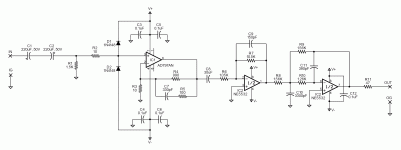
I've attached the revised schematic according to Samuel's recommendations.
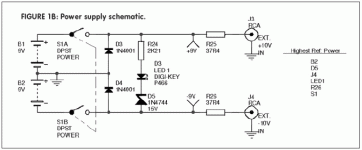
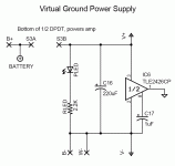
What is the quietest method of splitting the rails? I've seen the use of diodes (e.g., in the AudioXpress LNMP PSU attached) and have also seen the use of ICs such as the TLE2426 (e.g., in Tangent's LNMP PSU attached). Suggestions?
Thanks,
Bryan
What is the quietest method of splitting the rails? I've seen the use of diodes (e.g., in the AudioXpress LNMP PSU attached) and have also seen the use of ICs such as the TLE2426 (e.g., in Tangent's LNMP PSU attached). Suggestions?
Thanks,
Bryan
Attachments
That looks good to me. Two 100 nF caps for the AD797 are enough and I'd add a 22k resistor at the input to ground to discharge the caps when you disconnect the amplifier from the PSU.
The 30 uF cap will be physically large which makes it prone to hum pick-up. I'd stick with 10 uF and increase the resistors if you really want that low a -3 dB frequency. But believe me: you won't see any difference in a full-bandwidth measurement, the HF noise completely dominates things. If you want to look into low frequency noise it's probably better to build a dedicated box, e.g. with a 0.1-10 Hz response.
Make sure to throw the overall filter design (i.e. both NE5532 halves) into sim for a quick frequency response check. Butterworth should show no peaking--due to rounding errors in the passives values a bit (< 1 dB) might happen.
With two batteries there is no need to "split" the rails--simply connect one end of each to ground. D3/D4 in the AX schematic are just reverse-protection diodes.
Samuel
With two batteries there is no need to "split" the rails--simply connect one end of each to ground. D3/D4 in the AX schematic are just reverse-protection diodes.
Samuel
I would forget about the LED, the AD797 is a little piggy with current and 9V's only provide 175mAH.
My error on the 10 ohm resistor, the caps are going to discharge through the 1.5k so it's unnecessary.
In some high quality audio test equipment like the Boonton 1120 you'll find that the input is protected from RFI with a small inductor, on the Tektronix AA5001 there's a couple hundred pF's on the front end.
My error on the 10 ohm resistor, the caps are going to discharge through the 1.5k so it's unnecessary.
Are you referring to the 10R in series with the input coupling caps and before the input protection diodes (labeled "R2" in the latest schematic)? That was suggested by jcx to limit current to the AD797 during charging of the input coupling caps.
-Bryan
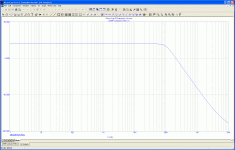
Make sure to throw the overall filter design (i.e. both NE5532 halves) into sim for a quick frequency response check. Butterworth should show no peaking--due to rounding errors in the passives values a bit (< 1 dB) might happen.
I simulated it using the free version of Microcap 9 and the results look good (attached). I'm not very experienced with simulating circuits, so I've attached the circuit in case anyone wants to double check my work...
-Bryan
Attachments
- Status
- Not open for further replies.
- Home
- Amplifiers
- Solid State
- Filters For Low-Noise Measurement Preamplifier
