I am building a two stage tube amp using a full wave bridge rectifier. Full output would go to v2 and for the reduced voltage for v1, I would like to use the neg. leg of the rectifier.
Here are my questions:
1) Is this possible?
2) Are there special considerations for this type of filtering for either leg to keep the hum down?
3) Since the transformer has a higher output than needed for v2, I am considering using a choke filter system, also for better regulation.
Thanks for your help.
Without a center tap on the secondary winding, you must use all four diodes as a FWB.
Do you want a positive voltage and a negative voltage, or two different positive voltages?
If you ground the center output, you get a positive voltage and a negative voltage.
If you ground the lower output end, you get a large positive voltage, and a half positive voltage.
A voltage doubler topology would also work either way.
Last edited:
Thanks.
Any reason to think that it would not work with tubes and high voltages? Are there any special considerations for this design under these circumstances?
Would a voltage doubler network work any better? Be quieter?
Please describe or draw the voltage doubler circuit given the final output voltage for v2 should be around 1.1kv with a 239ma current draw; obviously v1 would get half of both.
Assume that my transformer has the necessary voltage and current required; no center tap.
thanks,
Without a center tap on the secondary winding, you must use all four diodes as a FWB.
Do you want a positive voltage and a negative voltage, or two different positive voltages?
If you ground the center output, you get a positive voltage and a negative voltage.
If you ground the lower output end, you get a large positive voltage, and a half positive voltage.
A voltage doubler topology would also work either way.
Can a tube run on a "negative voltage"? Or this is just a question about reference to ground? Is it in fact a negative voltage and the tube can't use it, then I would want two positive (and very quiet) voltages.
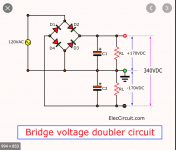
I have found a generic voltage doubler circuit.
thanks,
Can a tube run on a "negative voltage"? Or this is just a question about reference to ground? Is it in fact a negative voltage and the tube can't use it, then I would want two positive (and very quiet) voltages.
I have found a generic voltage doubler circuit.
thanks,
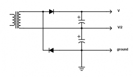
Since the winding is floating (no center tap), any node of the bridge rectifier circuit can be grounded.
To get two positive voltages (one half of the other), you ground the lower output of the three.
Then there are no negative voltages, since the center output is at +V/2, and the top output is at +V.
Last edited:

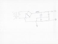
please find attached the image of the v. doubler circuit.
That's a full wave bridge (FWB) circuit. The lower output should be grounded instead.
So you are saying that this schematic would work. From my understanding:it seems that there are two positive voltages: the total top and bottom give the HV B+ and just the top section will give the lower voltage B+ .
Do I understand this correctly?
Look at the markings carefully.
All voltages are with respect to ground.
You cannot connect a circuit between the top two nodes, since
that circuit would have to be floating (not connected to anything else).
Top node = +V with respect to ground. (for the HV output stage)
Middle node = +V/2 with respect to ground. (for the input or driver stage)
Lower node =0 volts or ground. (this is the main audio ground point)
Last edited:
Are you saying that this schematic would work as long as the + and - voltages remain correct as described?
Another question: since we are talking about a HV circuit of around 1kv, the total voltage that any one capacitor would need to handle would be 1000v, correct? Or can C1 be 500v and C2 500V?
Another question: since we are talking about a HV circuit of around 1kv, the total voltage that any one capacitor would need to handle would be 1000v, correct? Or can C1 be 500v and C2 500V?
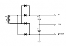
ON close examination, it seems that the circuits are the same but drawn differently.
But the question remains on the voltage of the caps: should they all be the total voltage for the circuit, or can they be half the voltage depending on their location and total voltage drawn?
But the question remains on the voltage of the caps: should they all be the total voltage for the circuit, or can they be half the voltage depending on their location and total voltage drawn?
Erm, B+ is positive. How can a negative voltage possibly provide B+?
Hi Mark,
Ok, so they are not the same circuits. Given the circuit below, can it provide two positive voltages? If so, how? And if it can, what size voltage caps should I have on it: the total voltage on the circuit? or can they be split to add up to the total voltage? Thanks.
Attachments
- Status
- This old topic is closed. If you want to reopen this topic, contact a moderator using the "Report Post" button.
- Home
- Amplifiers
- Tubes / Valves
- filtering neg leg of a bridge rectifier