Is the corrected Wilkinson filter the filter described in the cited paper or a corrected version of that?
We start with the apodization by a cos2 function already shown in Fig. 4 and repeated in Fig. 11(a). The passband is curved rather than flat, but a correction filter having a form such as (2 cos2) [Fig. 11(b)], can flatten the pass- band substantially, as shown in Fig. 11(c). We shall now push this principle to higher orders, following an approach similar to that described by Wilkinson [8].
The two works by Wilkinson that Craven refers to are:
[8] R. H. Wilkinson, “High-Fidelity Finite-Impulse- Response Filters with Optimal Stopbands,” IEE Proc-G, vol. 120, pp. 264–272 (1991 Apr.).
[9] R. H. Wilkinson, “High-Fidelity FIR Filters Based on Central-Difference Operators,” IEE Proc. Circuits Devices Syst., vol. 141, pp. 111–120 (1994 Apr.).
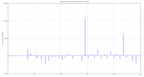
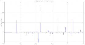
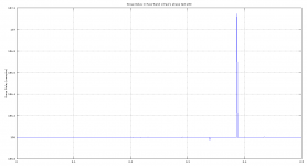
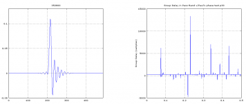
Messing about with SoX’s group delay plotter. Not sure if the result actually can tell us anything?
Used Paul’s phase test files from post #524. Using autoscale on axis see how p50 (-L) scales samples differently than the other two.
Used Paul’s phase test files from post #524. Using autoscale on axis see how p50 (-L) scales samples differently than the other two.
Code:
 figure(1)
 subplot(111);
 Fs = 352800;     % sampling rate
 [gd,f] = grpdelay(b,1,[],1);
 plot(f,gd);
 title(sprintf('Group Delay in Pass-Band w/Paul''s phase test p0'));
 ylabel('Group Delay (samples)');
 axis([0.2, 0.8, 400, 650],'auto');
 grid('on')
Attachments
Messing about with SoX’s group delay plotter. Not sure if the result actually can tell us anything?
Used Paul’s phase test files from post #524. Using autoscale on axis see how p50 (-L) scales samples differently than the other two.
Group Delay is a time delay vs frequency. It's same as phase delay.
https://ccrma.stanford.edu/~jos/fp/Group_Delay.html
For linear phase responses, for some constant, the group delay and the phase delay are identical, and each may be interpreted as time delay. If the phase response is nonlinear, then the relative phases of the sinusoidal signal components are generally altered by the filter. A nonlinear phase response normally causes a ``smearing'' of attack transients such as in percussive sounds. Another term for this type of phase distortion is phase dispersion.
So you are trading time smearing as a result of pre-post ringing with Linear Phase filters for time smearing as a result of group delay with intermediate and minimum phase filters.
The delay is given in samples, so you could convert this to time by dividing by the sampling rate.
Code:
 plot(f,gd/(Fs/1000));
 title(sprintf('Group Delay in Pass-Band w/Paul''s phase test p0'));
 ylabel('Group Delay (ms)');
Last edited:
Just to put any "challenges" into context of the real world I thought it might be worth posting this quote from Mike Moffatt from Jaffar's link...
Any avoidance of the Parks-McClellan pablum requires a lot of original DSP work. Am I a prophet who received the tablets from God or some other high-end audio drivel. Hell, no. I was the producer and director of this project and worked with Dave Kerstetter (hardware-software), John Lediaev (Math), Tom Lippiat (DSP Code), Warren Goldman (Coefficient Generator and development tools) for a total of 15 or so man years. These folks either taught math at The University of Iowa, Computer Science at Carnegie-Mellon University, worked at think tanks like the Rand Corporation – you get the idea. We did this for no money - What we all had in common was that we loved audio. All other audio pros were interested in Parks-McClellan and pointed and laughed at us. That's the way it happened.
Well then, there are no doubt which plots are the easiest to make sense out of.
There are more good things coming from Denmark other than Søren’s dam1021. Eivør is fast becoming one of my favorite female singers
https://soundcloud.com/eivor
First track that got me was 'Falling Free', - simplicity wrapped in power. And the way she jump octaves in 'Boxes' gets to me every time. Lately 'Green Garden' is growing on me.
Attachments
I think Mike wants to illustrate with the fan that if you apply a filter to DC the only influence of the phase (to the equally DC) output is its sign.
OK I take up the gauntlet ... that far that I give an "translation" for humans of relevant parts of the first section. I don't think it is worth the time spent. I do and can not say much about the relevance for the sound.
Thanks for taking the time to make the translation. It doesn't really reveal much about what they have done, but it gives a slightly better understanding of how they have approached the issue.
The Wilkinson article "High Fidelity Low-Pass FIR filters" is primarily about processing data from precision instrumentation. This is the abstract:
The paper describes a method of designing a low-pass finite-impulse response (moving-average) filter having a flat passband and an arbitrarily contoured stopband. The method effectively separates the design of the passband and the stopband, with independent control over the properties of each. The filter causes a controllably small amount of distortion when applied to a smooth input and is especially useful in connection with data rate conversion in those cases when the object is to process with precision a low-frequency signal. The method permits direct placement of stopband zeros, convenient for locating "don't care" bands in first stage data-rate-reduction filters, or suppressing large discrete sources of interference. The theory depends on the expansion of the filter weighting sequence (impulse response) as power series of central-difference operators.
I have cross-read the Wilkinson articles. He describes how to design low pass FIR filters that have a monotonous (i.e. not rippled) passband and which do not distort polynomial signals up to an given degree (of length at most the filter length). In the first paper this is done for symmetrical (i.e. linear phase) filters. In the second paper he does it for asymmetrical filters, keeping the phase in the passband next to linear but does not care in the stop band. Moreover he describes how to shape pass- and stop band if you do not want it "flat".
Parks-McClellan in contrast has (by design) passband (and stop band) ripple. You can bound the passband ripple by design to any number you want.
Wilkinson mentions that in his filters, when implemented in real, due to arithmetic precision, a very small passband ripple may be introduced.
In both, Parks-McClellan and Wilkinson, the filter coefficients are given implizit, as solutions of a set of equations. In general they are computed by numerical approximation. If you make the requirements special enough you may be able to solve the system explicitly, i.e. get the coefficients in closed form.
In light of this, for Mike Moffatt closed form filters, "they" must have made enough restrictions to be able to solve the coefficient equations explicitly (even if they use an other approach as Parks-McClellan or Wilkinson). Restrictions must not be a bad thing if they are adequate for the problem.
However I wonder: Wilkinson's articles are 20 years old. He had an implementation of his design algorithm at that time. There must be available filter design algorithms that use Wilkinson as an option or are that general that the "Wilkinson-type" filters are included as a subcase.
What software tool are you using to generate the ASCII file which can be converted to .skr with the tool provided by Soren?
Can I use Rephase and then cut and past the respective frequency sections?
Would it be possible to create a filter which will allow for acoustic/loudspeakers correction, has someone tried this?
It looks to be possible to use the REW software to generate a filter in combination with the MINIDSP UMIK-1 microphone and then to load into Rephase
http://www.minidsp.com/applications/advanced-tools/rephase-fir-tool
Use mkrome.exe download from Søren’s place.
Copy paste to dam1021.txt file also downloaded from Søren.
We are waiting for Søren to release firmware where we get IIR crossover and room correction in addition to 4 selectable FIR filter selections for each fs.
Copy paste to dam1021.txt file also downloaded from Søren.
We are waiting for Søren to release firmware where we get IIR crossover and room correction in addition to 4 selectable FIR filter selections for each fs.
We are waiting for Søren to release firmware where we get IIR crossover and room correction in addition to 4 selectable FIR filter selections for each fs.
Now, that got me thinking on something John Swenson said.
Looking at the spec sheets for the DAC chips you can tell that they are using cascaded filters. When I use an external FPGA to implement a filter and program it to be cascaded multiple filters, I hear a similar sound, when I implement a simple filter (no cascading) I get the better sound. The conclusion seems to be that it is somehow the cascading of filters that causes the problem. Again no clue at all why this is so, what the mechanism is etc.
Upsampling Impressions - Page 3
As I plan to use dam1021 as crossover and preamp I should possible listen closer at his claims.
Now, that got me thinking on something John Swenson said.
As I plan to use dam1021 as crossover and preamp I should possible listen closer at his claims.
It's a bit pointless as you can't change the internal architecture of the DAM.
It's a bit pointless as you can't change the internal architecture of the DAM.
So you think pass through filters will give same issues as cascading filters?
Edit: To clarify a little. Current setup are crossed in the 200Hz range. My thinking is that it should not be necessary to clutter the low frequency range with something optimized to reach Nyquist?
Last edited:
Now, that got me thinking on something John Swenson said. ...
An effect that I see that could cause that, is that cascading of two FIR filters might result is a loss of arithmetic accuracy, especially with long filters with lots of very small coefficients.
The convolution in the FPGA is done with a multiplier-accumulator (MAC). The MAC has that many bits of precision (67 in the DAM) that the arithmetic of the convolution is performed exact (if the parameters have been chosen right). This is necessary as otherwise the addition of lots of tiny numbers would lead to noticeable errors. I am quite sure that the result of the convolution is truncated to the ordinary word length (so from 67 to 32 bit in the DAM) before being further processed (e.g. as the second MAC expects that as input). That is the possible source of error introduced in cascading: the second filter is supplied with that truncated intermediate result instead of the exact one. I have not yet thought about how much error can be introduced that way, perhaps none noticeable, as we end up with only 28 bit precision anyway. That depends much on the actual implementation, with other DACs the error could be more noticeable, e.g. if they use only 24-bit as signal word length (also in-between the FIRs).
If you implement the filter in one step the whole computation is done in one MAC and thus exact.
If one filter is NOS or bypass cascading will have no negative influence. If one Fiter is a short filter with "big" coefficients, it is unlikely that there is an influence.
With high oversampling rates, implementing the filter in a single step makes the filter much longer and exceed the resources of the FPGA.
I have not yet thought about how the IIR is implemented, so can say nothing about cascading with IIR filters.
... the whole computation is done in one MAC and thus exact. ....
.. the whole computation is done in one MAC and thus less erraneous. ..
?
//
i.f-fixed point floats are the numbers 2^{-f}*x where x is a (i+f)-bit signed integer (the sign counts as one bit)... the whole computation is done in one MAC and thus less erraneous. ..
?
//
You can multiply i.f-fixed point float with a j.g fixed point float exact in a
(i+j-1).(f+g) fixed point float.
In the DAM the coefficients are 2.30, the signal worst case 1.31. Thus if you configure the MAC as 6.61 fixed point float, the multiplication is exact. Moreover that leaves you with 4 bits headroom for the addition.
As the signal should not clip with a well formed filter it is verrrry unlikely that you exceed temporarily the headroom while adding ... thus the total convolution is exact.
The only error is then truncating the MAC result to the output format (and before that converting the coeficents in fixed point floats)
Last edited:
However I wonder: Wilkinson's articles are 20 years old. He had an implementation of his design algorithm at that time. There must be available filter design algorithms that use Wilkinson as an option or are that general that the "Wilkinson-type" filters are included as a subcase.
I haven't been able to find one as yet. Julian Dunn made the observation in 1998 that Wilkinson's "high-fidelity" filters were little used in audio. This thread is one of the top hits if you try to google for references to these filters.
Dunn mentions another bit of software - METEOR - that allows filter specification with no passband ripple.
The c code and paper is available from Ken Stieglitz's webpage: https://www.cs.princeton.edu/~ken/meteor.html
There is also semi-maintained version which implements more of the features discussed in the paper called gmeteor:
gmeteor Home Page
I had to make mods to a number of files to get it to build on OS X plus install an old version of guile through macports. I'll reserve judgement on whether it was worth the time spent...
Add: seems not, guile running at 100% cpu and no indication of what is happening. I'll give it a try with a vm of RH6.1, and see how that goes...
Last edited:
The main asset of Wilkinson is not that he produces passbands with no ripples (that seems to be doable "before him") but that he can produce passbands as flat (or better as smooth) as you want (by choosing a parameter). That is a property of controlling the higher derivatives of the function and e.g. guarantees that polynomial signals up to an given order pass undistorted.
The problem that I see is not that it is hard to compute these filters (if it was doable 20 years ago, now it can be probably done with you coffee machine). The problem is most likely that you get these extra properties not for free, e.g. the filters get long (already the examples in his paper are long). One point in his second paper was that due to asking next to linear phase only for the passband gives shorter filters.
Meteor can produce unrippled passbands, but has not that quality control as Wilkinson, as far as I see.
context of filters
I don't think it's 'off topic' to ask at this point a question about the real world context in which all these filters stand. If it is about perfect music reproduction in our listening room with this specific DAC how come that the calculations can be done without reflecting the reality of music recording and/or reproduction in the individual set ups? I use room correction (PEQ & physical traps) and some of these filters are powerful enough to throw off quite a bit of my otherwise perfect balance (crap series, MB3 for instance).
I can hear the tiniest difference between filters but shouldn't they keep the overall room balance untouched and only change the behavior of the DAC? I am only talking about what seems to be phase related not about amplitude/frequency which is always o.k. in my room no matter which filter. I use my analog system (vinyl) for cross checking my room response and it's predictable and reliable with all kind of recordings.
And how could filters which can throw off phase quite a bit (some create a deeper space like analog while others sound flat) ever reflect the real studio situation where much attention is given to keep the correct phase between tracks and on the other hand define the character of the mix in many positions by adding delay? What is the reference point for checking these filters and is there one at all? Or does it all boil down to individual taste in the end and nothing matters?
No idea if this is useful, but they’re done to work with Matlab.
I. W. Selesnick and C. S. Burrus, Exchange Algorithms for the Design of Linear Phase FIR Filters and Differentiators Having Flat Monotonic Passbands and Equiripple Stopbands, IEEE Trans. on Circuits and Systems II, vol. 43, no. 9, pp. 671-675, September 1996.
These programs are for the design of symmetric FIR filters achieving specified Chebyshev errors in the stopband and a specified degree of flatness in the passband.
FIR and IIR Filter Design Algorithms | Rice DSP
For diyAudio I would say that is the general rule. All the talk is to learn the rules and tools so we understand how to adjust to taste.Or does it all boil down to individual taste in the end and nothing matters?
Meteor can produce unrippled passbands, but has not that quality control as Wilkinson, as far as I see.
I don't think that Meteor is worth pursuing TBH. The original code compiles without any drama's and runs well, but I was struggling to produce anything very useful due the limited number taps.
- Home
- Source & Line
- Digital Line Level
- Filter brewing for the Soekris R2R