If you can get the old relays out safely and the new in then I think I would go down that route and also up the value of the cap. Doing all that has to be a surefire fix 🙂
Good Morning Mooly,
I had a final question:
I was maybe put on the wrong foot by the Cambridge Service Bulletin, suspecting that the control of the Mute Relays could be the only suspects for failing Audio Channel output in the Cambridge AZUR 840C.
In this CD player/DAC, there are two main Relays RL1, RL2 which are switched ON, once the Standby Switch is operated.
These relays switch 4 secondary transformer windings (of the mains transformer) to 4 Graetz bridges ( for analogue and digital supplies for the Left and Right Channel), see schematic.
If the analogue supplies are wacky (due to bad relay contacts): a failing Audio output at the Audio terminals will manifest itself , as well (simply because the DAC and the OP AMP's of the channel do not get adequate power supply.
I intend to replace these two relays RL1 and RL2 (Massuse ME-11-5) as well.
My questions:
1) they are fed by a resistor R160 (32 Ohm) and switched by Transistor Q6
However, there is no "kick in "capacitor installed , unlike the circuit of the mute relays, which we discussed earlier.
Would it therefore be useful to add a capacitor (say 1500 uF 63V)??
2) Would it help to protect the relay contacts by 4 snubbers (each : 0.1 uF 250V + 120 Ohm)
Admittedly, there is no inductive load, but I have seen a discussion on EEV blog indicating that nevertheless it might help protecting the relay contacts.
Thank you for your advice!
regards, Martin
Attachments

The 32 ohm should be sized so that it gives the correct coil voltage when they are energised. That's the first thing to check, that the voltage across the coil agrees with the relay markings.
Adding a cap would increase the initial closing force as it would pulse the relay with 10 volts for a few milliseconds.
If you can replicate the fault then its always best to try and take some measurements to confirm your suspicions. You could add some leads from suitable points to monitor and then use the player normally until the fault shows and then measure the voltages on the test leads for absolute proof.
If the contacts are switching the raw AC from the secondary then I suppose a snubber might reduce arcing under some conditions although tbh relays used for higher current switching tend to not have intermittent issues like those switching very low value signals .
Best to confirm by measurement where the problem is first.
Also don't overlook such things as dries on any of the regs etc that run hot. They can be really hard to spot sometimes and need a magnifying glass to spot any cracks in the solder.
Hi Mooly,
Thanks for your fast response!
1) Specifics for the Relays Massuse ME-11-5 are:
Rcoil = 62 Ohm Icoil=80 mA Vcoil=5V
With R160=32 Ohm (original design), each relay only receives 74 mA (93% of nominal value)
When I opened the player some time ago, I did already decrease the value of R160 to 27 Ohm (5W) , which now results in a total current of 160 mA (80 mA per Relay) = 100% of the nominal value).
Your first remark had thus been addressed already.
2) I understand that you endorse additional installation of the "Quick start" Cap (say 1500 uF 63V)
and
That you also approve installations of snubbers (0.1 uF, 250V +120 Ohm) across each of the 4 relay contacts.
3) I agree that one should try to replicate the fault condition and next measure (DMM, Scope), what's going on.
I have started to try to reproduce the fault a few days ago (quite time consuming, since I have to wait each time one day, to replicate a "Cold Boot")
What I have found so far:
A) when I switch ON with the "Master Switch " , wait 60 seconds, and activate the "Stand By "switch, the AZUR 840C starts and plays flawlessly.
B) same for 30 and 15 seconds waiting time between "Master Switch" and "Stand-By " switch.
C) With only 5 seconds delay between "Master Switch" and "Stand by" switch activation, the fault manifest itself ( only noise in Left Channel)
I could reproduce this condition 3 times, so far.
NB.
If the "Master Switch" is switched ON, a PIC circuit on the front panel is started and the main power relays (RL-1 and RL-2) are switched almost instantaneously.
Depends on charging the 10V unregulated power circuit (4400 uF capacitors).
The Mute relays are only switched on after 7 seconds (determined by design).
So from the above, it might (maybe) concluded that the PIC circuitry needs more than 5 seconds to fully start up.
In that case there would have been no fault, only an Operator error (I should have waited long enough: say 1 minute after activation of the "Master Switch", before operation of the "Stand By" switch.
(FYI, the schematic of the PIC controller.
Button "SW1 (standby) is the Stand-By On/Off switch
The Mute control signal is fed Via CN7 (#1) to the transistor controlling the Power relays RL1 and RL2
The 5V for the PIC circuitry is derived from the 10V unregulated:
So either the 5V has not fully charged yet (4400 uF capacitors not fully charged yet), or the PIC needs a finite time, at least 10 sec to start up).
Thank you for all your help. Very much appreciated!
Attachments
If you solder wires to all the points of interest and bring them out of the player then you will be able to measure all the suspect areas in one go while the player is faulty.
Snubbers as you suggest can not do any harm but I don't think they will influence the fault or change the way a new contact may (or may not) degrade.
I can't see the PIC taking a long time to reset and in any case that surely could not cause a channel specific issue. Tbh, noise in one channel only seems more likely to a be problem around that channels audio circuitry and DAC. Maybe freezer spray might reveal something there.
Mooly,
Thanks again; Measuring is knowing! Otherwise, it is nigh impossible to diagnose a fault!
I will report back, once I have further diagnosed the fault by DMM voltage measurements and scope observations.
For my own learning, though:
If I brutely switch off the PIC (by using the "Master" switch only,
would the PIC then need more time to reset (once the "Master" switch is switched ON again, followed by Switching ON the "standby Switch",
Compared to the situation
Where I first use the "Stand-by" switch to properly switch OFF the PIC, followed by finally switching OFF with the "Master" switch ?
I could imagine, that in the second case the PIC will already have been reset properly and will start up quicker once the "Master" switch and next the "Standby" switch are switched ON, again.
BTW
The 8 NP 10uF Caps at the powerlines of the DAC's were also a known problem area (known by Cambridge) and were ( in later series) replaced by better quality Japanese capacitors (FujiCon).
If the DAC is out of balance, it will apparently generate such noise.
So 2 known problems: Capacitors in the Powerlines of the DAC's and a poor capacitor the RL-1, -2 -3 Mute circuitry, both attributable to poor Chinese Capacitors (and maybe poor quality Relays).
That's a pity, because it spoiled a nice CD Player/DAC and was presumably not good for Cambridge Audio's reputation.
Wishing you a Happy Eastern & Stay healthy!
Attachments
Wishing you a Happy Eastern & Stay healthy!
And yourself... thanks 🙂
Now I would have thought that the PIC was never reset once powered up. I haven't studied all the power lines and what controls what but normally only a mains on/off would reset a uProcessor. Switching between on and standby usually leaves much of the circuitry still powered.
Resets of uP's take microseconds but what happens next depends on the internal program and what initialisation routines are run before the machine appears to respond normally. Some equipment is frustratingly slow to initialise but that is different to it showing a fault such as you have.
Hi Molly,
Some feedback and a question.
The AZUR 840C CD Player/DAC has proved to be consistently reliable for a week (no Caps changed out, yet; Still Waiting on Parts), by adopting a strict Start-Up Procedure:
1) The apparatus is fully switched off.
2) Switch main Power switch (at the back) ON and wait 15 seconds (at least 10 seconds): The PIC is started from a +5V line (from an 7805); 10V Unreg is also present.
Apparatus is now in Stand-By Mode.
3) Now Power on the Apparatus from Stand-By to ON by the On/Standby Button on the Front Panel.
4) The Main Power Relais (RL1, RL2) switch on (4 Power rails to the DAC's and OpAmp's are started) plus power from the +/- 10V unreg (via stabilizers ) to the DSP (3.3V and 1.2V ) and a 5V (digital Line) to both DAC's.
5) After some 5 seconds the apparatus switches automatically the 3 Mute Relais and the apparatus is now fully functional.
I could consistently provoke a failure ("dim" Channel) by not waiting long enough ( < 5 seconds) in step 2, before going to step 3.).
Since I had hooked both the RCA Output and the XLR outputs to my amplifier, I could diagnose that the wacky channel is on both the same ( L or R) RCA and the XLR output (so one of the 3 Mute Relays is NOT the cause of the "Dim" Channel).
The in-built delay (5 seconds) of the 3 Mute Relays is either built in electronically or by the software in the PIC of the Front Panel.
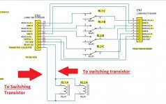
Please have a look at figure 1.
Q4 (the switching transistor of the Mute Relays RL1, RL2 and RL3) are either operated by the RELAY line (from a PIC output ) via Q8 or the Line OE1 via Q2 (also from an output from the PIC).
So, I reason that either one or both lines (RELAY or OE1) can activate Q4 (and the Relays RL1, RL2 and RL3) ;
The observed automatic 5 seconds delay (between pushing the ON /Standby switch) might therefore be software dictated (by the PIC).
However, I fail to understand the purpose / function of the components in the Green / Dotted circle, which are also hooked up to the Base of Q4.
Would it be possible that you could enlighten me here?
NB.
The AC_5V is 5V AC which is available once the Main Power switch at the back is switched ON.
NB 2.
Capacitor C212 is actually 10 uF , NOT 1 uF (Typo in the diagram);
It is 10 uF on the actual board and also on the PCB component listing.
So All in All, the 840C CD Player DAC seems to work now consistently (having adjusted the serial resistors of the Mute and Power relays), but it still needs a certain operating routine (waiting 15 seconds before operating the On/Standby switch on the Front Panel).
If I leave the rear main power switch always ON, the ON/Stand-by switch on the Front and the 840C itself seems to work consistently.
So, hence my question regarding the function of schematic 1.
Any help would be very much appreciated!
Some feedback and a question.
The AZUR 840C CD Player/DAC has proved to be consistently reliable for a week (no Caps changed out, yet; Still Waiting on Parts), by adopting a strict Start-Up Procedure:
1) The apparatus is fully switched off.
2) Switch main Power switch (at the back) ON and wait 15 seconds (at least 10 seconds): The PIC is started from a +5V line (from an 7805); 10V Unreg is also present.
Apparatus is now in Stand-By Mode.
3) Now Power on the Apparatus from Stand-By to ON by the On/Standby Button on the Front Panel.
4) The Main Power Relais (RL1, RL2) switch on (4 Power rails to the DAC's and OpAmp's are started) plus power from the +/- 10V unreg (via stabilizers ) to the DSP (3.3V and 1.2V ) and a 5V (digital Line) to both DAC's.
5) After some 5 seconds the apparatus switches automatically the 3 Mute Relais and the apparatus is now fully functional.
I could consistently provoke a failure ("dim" Channel) by not waiting long enough ( < 5 seconds) in step 2, before going to step 3.).
Since I had hooked both the RCA Output and the XLR outputs to my amplifier, I could diagnose that the wacky channel is on both the same ( L or R) RCA and the XLR output (so one of the 3 Mute Relays is NOT the cause of the "Dim" Channel).
The in-built delay (5 seconds) of the 3 Mute Relays is either built in electronically or by the software in the PIC of the Front Panel.
Please have a look at figure 1.
Q4 (the switching transistor of the Mute Relays RL1, RL2 and RL3) are either operated by the RELAY line (from a PIC output ) via Q8 or the Line OE1 via Q2 (also from an output from the PIC).
So, I reason that either one or both lines (RELAY or OE1) can activate Q4 (and the Relays RL1, RL2 and RL3) ;
The observed automatic 5 seconds delay (between pushing the ON /Standby switch) might therefore be software dictated (by the PIC).
However, I fail to understand the purpose / function of the components in the Green / Dotted circle, which are also hooked up to the Base of Q4.
Would it be possible that you could enlighten me here?
NB.
The AC_5V is 5V AC which is available once the Main Power switch at the back is switched ON.
NB 2.
Capacitor C212 is actually 10 uF , NOT 1 uF (Typo in the diagram);
It is 10 uF on the actual board and also on the PCB component listing.
So All in All, the 840C CD Player DAC seems to work now consistently (having adjusted the serial resistors of the Mute and Power relays), but it still needs a certain operating routine (waiting 15 seconds before operating the On/Standby switch on the Front Panel).
If I leave the rear main power switch always ON, the ON/Stand-by switch on the Front and the 840C itself seems to work consistently.
So, hence my question regarding the function of schematic 1.
Any help would be very much appreciated!
Attachments
Last edited:
Q4 needs a positive voltage available on its base in order to turn on the relays. That is provided by the circled parts direct from the AC winding on the transformer.
The small time constant of the reservoir cap (C212) means that the supply collapses extremely quickly when power is turned off or if there is a mains dropout and that enables the mute relays to activate near instantaneously.
Q2 and Q8 that control the relays normally can only pull that voltage down (turn off the relays) but as their supplies will have a much larger time constant they can not be used to rely on muting the output fast enough when power drops out.
Its worth saying that caps like C212 can in some cases have a fairly short life due to relatively high ripple currents in a small value cap although in this case R145 is big enough to limit that.
D18 is to ensure a quick pull down of the base voltage of the relay driver transistor when power is removed.
Hello Mooly,
Fully understood! 🙂
Thank you so much for providing all your time to explain this circuit and other particulars of the design of the Cambridge AZUR 840C.
Wishing you : All the Best!
Again, many thanks,
Martin
Fully understood! 🙂
Thank you so much for providing all your time to explain this circuit and other particulars of the design of the Cambridge AZUR 840C.
Wishing you : All the Best!
Again, many thanks,
Martin
I enjoyed reading this but noticed one misunderstood thing.
Across Europe, though we harmonised the mains voltage across the territories, nothing actually changed. Changing the supply voltage would screw up all of the power factor correction installed across every inductive device in industry (there are a lot of induction motors across Europe!).
Here is a brief explanation of what was done:
Leads Direct | What is the difference between UK voltage and European voltage
Rather than being patronising, I thought the DIYers would find that interesting as it's not obvious if you don't deal with this stuff for a living.
Very true although in my area things have changed a little in that we now have some kind of active voltage control that reduces voltage at times of peak demand (apparently) in an effort to reduce overall loading on the network.
There was a trial run locally across several postcodes for a couple of years where they asked people to report anything unusual before the system officially went live (lol so to speak 😀).
I can't find anything on it now so don't know if it was widely adopted or not.
There was a trial run locally across several postcodes for a couple of years where they asked people to report anything unusual before the system officially went live (lol so to speak 😀).
I can't find anything on it now so don't know if it was widely adopted or not.
@ Twelveeyedfish,
Unfortunately I cannot agree with you :
At present we have, here in the Netherlands a mains of 230V AC Nominal, 50 Hz, and from my own measurements in my House, I can contest that that norm is accurately kept (I typically have only some 1.0-1.5V V deviation (+/-) across the day; at night, my mains voltage is exactly 230.1 V in my Home).
Some 20 years ago, when I bought this professional DMM, which I still use ( we were still in the 220V Era), I measured the house voltage also and concluded that it was very close to the nominal 220V at that time (deviations of +/- 2 V measured).
We were promised by the Electricity Co. that the mains voltage would be gradually increased in 1 V steps over a 10 year period (from 220V to 230V AC).
Not so: it was abruptly changed from 220V -> 230V , which induced a lot of early failures of the Light Bulbs at the time.
Hence, all Tapeheads on the TapeDeck Forum in Holland change their Voltage selectors of their old equipment (Tapedecks, but certainly Amplifiers) from the old 220V setting to the former "British" setting of 240V.
(Sometimes one has to open the equipment and swap a tap on the transformer to cater for this change (no setting of the mains voltage possible at the back for some equipment).
Invariable, if one does not make this change, the equipment runs hotter (especially Eddy Current Motors) and bulbs like Vu meter lamps fail much earlier.
So IMHO, we at the Continent were the Loosing Party, in this "Power Harmonization Exercise".
From my own experience in Malaysia (240V AC, 50 Hz) , I know that the Dutch and German Expats, which kept their equipment at 220V typically had a fried / failed TV, Radio, Amplifier within one year.
Before, I went abroad, I bought a large Autotransfomer with many taps, so I could adjust the supply for my HiFi, TV etc. to 220V.
It served me well for 5 years in the Tropics.
I still use that transformer to keep all my HiFi gear hooked up to at a nominal 210V; better safe than Sorry, although theoretically the equipment should be able to cope with the current 230V .

The big question is how a supply holds up under load... such as (in my case) when loaded with off peak heating:
3.4kW + 3.4kW + 2.55kW +2.55kW = 11.9kW for several hours added to which 3kW + 2kW + 0.85kW + 3kW can also be added.
Total loading give or take = 20.75 kw or around 90 amps.
3.4kW + 3.4kW + 2.55kW +2.55kW = 11.9kW for several hours added to which 3kW + 2kW + 0.85kW + 3kW can also be added.
Total loading give or take = 20.75 kw or around 90 amps.
Hi Mooly,
That's an impressive electricity consumption!
Are you heating your home with electricity??
Here in the Netherlands, we are (still ) using natural gas for heating the house.
The largest electricity consumers are the washing machine, tumble dryer and the dishwasher (each some 1.5 - 2 KW).
My house connection is 3 Phase 400V~ (50 Hz), 25 A per Phase (which is 230V 50Hz 25 A for one phase).
The house connection has 8 (230V) groups with 2 earth circuit breakers (one for 4 groups) ;
I have put the HiFi plus the TV on one dedicated group, of which (as I already reported) the voltage remains Rock Solid (within +/- 1 V of the nominal 230V AC).
This group stays also stable, independent of "heavy" consumers on the other groups.
But the issue, I really wanted to post was that :
1) Apparently in the UK, the Electricity Board pretended that they would not change the 240V voltage during the "Harmonization with Continental Europe"
(only modifying the specification envelope)
whilst
2) The Electricity Board in NL promised they would only gradually change the mains voltage with 1 V / year over a 10 year period (from 220V - > 230V).
As I reported, in reality, around 2004, they actually implied here a step change (from 220V -> 230V ) which was quite noticeable by the sudden very high incidence of failures of Light Bulbs (their life expectancy is exponentially decreased at higher voltages).
No doubt, it affected other appliances as well.
My point was that the Electricity Board would let us to believe that the Voltage change/increase ("Harmonization") would not affect the consumers (no doubt to avoid legal issues), but in reality it DOES reduce the lifespan of older 220V equipment.
It is thus better for an older appliance to adopt it for the higher mains voltage by changing the power selection (at the back) to 240V .
(I remember as a kid the story of a family which had a (tube) TV which broke down very frequently)
It turned out their house was next to the transformer house of the electricity company and their mains was 245 V instead of the nominal 220V!
Their TV failed every 3/4 year! Eventually , the TV was adopted for the higher mains).
Sorry to have moved outside the original topic.
(Still waiting on Spare Parts, but the AZUR 840C CD Player/DAC refuses to breakdown). It plays very nicely (I found out that the symmetrical XLR outputs even sounded somewhat better!).
In the meantime, I have found on this Forum (and others) the most prevalent culprits of those failing (Chinese) electrolytic caps.
Most noticeably in the various Digital and Anolog power supply lines for the DAC's).
I will continue the overhaul with Film Caps, once the fault manifest itself again.
Again, many thanks for your help!
Cheers & Keep Fit,
Martin
BTW What do you think from these schematics:


NB
The + 10V_L is taken from a 10V Regulator (U44, LT1761) which is fed by + 15V , which is taken (higher upstream" ) from a 15V regulator, (U14, 7815).
It looks like the +15V is connected to the +10V by Resistors R93 and R94 (both ZERO Ohm) ;
If so, Isn't the 10V regulator (U44) bypassed and redundant????)
Most likely a typo : R93 (and it's counterpart R181) are indeed zero Ohm, but R94 (nor it's counterpart R180) are not available on the BOM).
R94 and R181 are both ZERO Ohm according to the schematic; But this doesn't jive.
Your opinion is most welcome!
That's an impressive electricity consumption!
Are you heating your home with electricity??
Here in the Netherlands, we are (still ) using natural gas for heating the house.
The largest electricity consumers are the washing machine, tumble dryer and the dishwasher (each some 1.5 - 2 KW).
My house connection is 3 Phase 400V~ (50 Hz), 25 A per Phase (which is 230V 50Hz 25 A for one phase).
The house connection has 8 (230V) groups with 2 earth circuit breakers (one for 4 groups) ;
I have put the HiFi plus the TV on one dedicated group, of which (as I already reported) the voltage remains Rock Solid (within +/- 1 V of the nominal 230V AC).
This group stays also stable, independent of "heavy" consumers on the other groups.
But the issue, I really wanted to post was that :
1) Apparently in the UK, the Electricity Board pretended that they would not change the 240V voltage during the "Harmonization with Continental Europe"
(only modifying the specification envelope)
whilst
2) The Electricity Board in NL promised they would only gradually change the mains voltage with 1 V / year over a 10 year period (from 220V - > 230V).
As I reported, in reality, around 2004, they actually implied here a step change (from 220V -> 230V ) which was quite noticeable by the sudden very high incidence of failures of Light Bulbs (their life expectancy is exponentially decreased at higher voltages).
No doubt, it affected other appliances as well.
My point was that the Electricity Board would let us to believe that the Voltage change/increase ("Harmonization") would not affect the consumers (no doubt to avoid legal issues), but in reality it DOES reduce the lifespan of older 220V equipment.
It is thus better for an older appliance to adopt it for the higher mains voltage by changing the power selection (at the back) to 240V .
(I remember as a kid the story of a family which had a (tube) TV which broke down very frequently)
It turned out their house was next to the transformer house of the electricity company and their mains was 245 V instead of the nominal 220V!
Their TV failed every 3/4 year! Eventually , the TV was adopted for the higher mains).
Sorry to have moved outside the original topic.
(Still waiting on Spare Parts, but the AZUR 840C CD Player/DAC refuses to breakdown). It plays very nicely (I found out that the symmetrical XLR outputs even sounded somewhat better!).
In the meantime, I have found on this Forum (and others) the most prevalent culprits of those failing (Chinese) electrolytic caps.
Most noticeably in the various Digital and Anolog power supply lines for the DAC's).
I will continue the overhaul with Film Caps, once the fault manifest itself again.
Again, many thanks for your help!
Cheers & Keep Fit,
Martin
BTW What do you think from these schematics:
NB
The + 10V_L is taken from a 10V Regulator (U44, LT1761) which is fed by + 15V , which is taken (higher upstream" ) from a 15V regulator, (U14, 7815).
It looks like the +15V is connected to the +10V by Resistors R93 and R94 (both ZERO Ohm) ;
If so, Isn't the 10V regulator (U44) bypassed and redundant????)
Most likely a typo : R93 (and it's counterpart R181) are indeed zero Ohm, but R94 (nor it's counterpart R180) are not available on the BOM).
R94 and R181 are both ZERO Ohm according to the schematic; But this doesn't jive.
Your opinion is most welcome!
Last edited:
Yes, all electric and no gas. About 88kWh a day in winter averaged over 28 days. Scary 😱
That diagram doesn't make sense unless they mean only one or the other is fitted.
That diagram doesn't make sense unless they mean only one or the other is fitted.
But the issue, I really wanted to post was that :
1) Apparently in the UK, the Electricity Board pretended that they would not change the 240V voltage during the "Harmonization with Continental Europe"
(only modifying the specification envelope)
whilst
2) The Electricity Board in NL promised they would only gradually change the mains voltage with 1 V / year over a 10 year period (from 220V - > 230V).
As I reported, in reality, around 2004, they actually implied here a step change (from 220V -> 230V ) which was quite noticeable by the sudden very high incidence of failures of Light Bulbs (their life expectancy is exponentially decreased at higher voltages).
No doubt, it affected other appliances as well.
My point was that the Electricity Board would let us to believe that the Voltage change/increase ("Harmonization") would not affect the consumers (no doubt to avoid legal issues), but in reality it DOES reduce the lifespan of older 220V equipment.
It is thus better for an older appliance to adopt it for the higher mains voltage by changing the power selection (at the back) to 240V .
This is all correct info but it is often misinterpreted. Then the next step was discussed which would be a harmonised 250V but that has not happened (yet).
Too much to read in this thread and discussed many many times but using solely large value MKS (polyester not polystyrene as I read) caps after 78xx/79xx regs is not wise.
Last edited:
Jean Paul,
Thanks for the feedback ( Were you serious about the "250V harmonization" or just a joke?)
"Harmonization" of the mains voltage to 250V" is IMHO a very bad idea and will no doubt result in a lot more accelerated appliance failures.
Seems more a designed "obsolescence activity" to keep the appliance industry going.
1)
Sorry for the long thread.
I should have kept it off the forum, but Mooly has helped me a lot to understand the schematic and it has identified as such a design weakness (improperly designed relay coil voltages)
Rectification seems to have cured my Player/DAC): a clear design error.
2)
Just to correct you:
I am not going to use solely MKS (polyester) capacitors (WIMA MKS2 4.7 uF 50) in lieu of the poor quality Chinese 10uF 35V ones.:
View attachment e_WIMA_MKS_2.pdf
The existing 100 nF capacitors at in- /output of the LM78XXX/LM79XXX regulators will be maintained. Hence there should be no stability issues with the LM7X XX regulators (I will check anyway with an anolog scope, if everything is well).
Can you specify why you think it is NOT a good idea?
3)
I'm fed up with changing out electrolytic capacitors which are systematically fried by high temps of heatsinks.
Cambridge already advised (in a service note) to (as a routine) change electrolytic capacitors in 10V and 5V analog power rails (of Op AMPS and DAC's).
The rest of those 10 uF capacitors in the digital circuitry will no doubt also fail in the near future.
Better to get rid of them, for once and for all.
(This player is just like an old British motorcycle: a Love / Hate relation.
After the design weaknesses have sussed out, you will eventually have a very nice product!).
Cheers, Martin
- Home
- Source & Line
- Digital Source
- Film capacitors i.o.f Electrolytics icm LM78xx regulators: Minimum Value required?