If you notice Dunlavy surrounded his tweeter with little strips of open cell foam.
But Dunlavy's tweeter doesn't have proper waveguide like yours, so the foam is more critical in Dunlavy than in yours. But you can add simple foam/felt around/on the waveguide termination.
Fair enough. I tend to find that correcting problems in a drivers frequency response with a minimum phase EQ also corrects the phase response. Persuading the 5MR450NDY to better follow a 1st order slope on the bottom end may help some. This may mean providing a significant boost in EQ to counter the drivers own acoustic roll off. Hitting the 1st order target for 1 octave either side of the crossover point should be good enough.No, I tried this last time with the other drivers and found that it requires too much PEQ that it sounded phasey yet did not make the SR any better. I find that this sounds best with minimal EQ and let the acoustical slope take whatever it ends up as. Just need to make it electrically LR2-BW1-LR2.
Last edited:
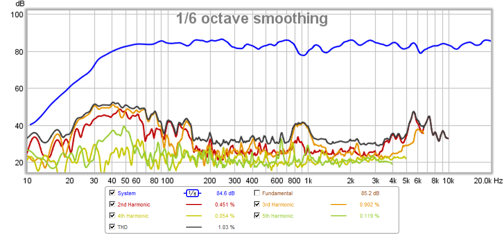
Do you have distortion graphs for this one?
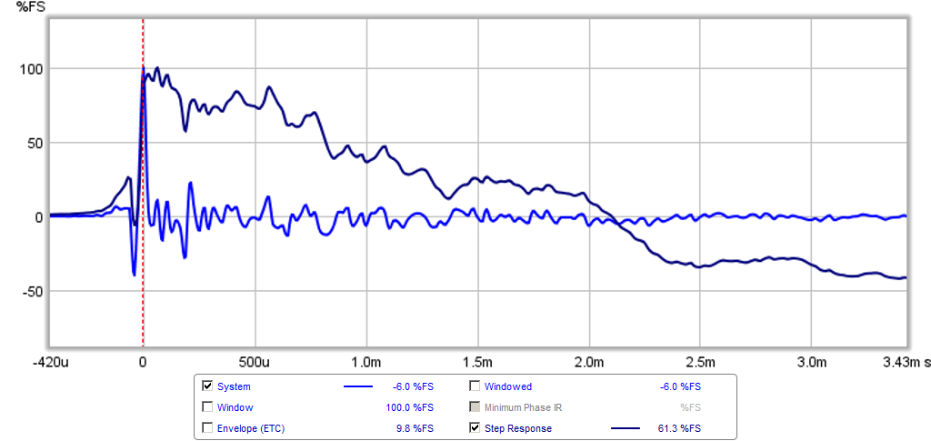
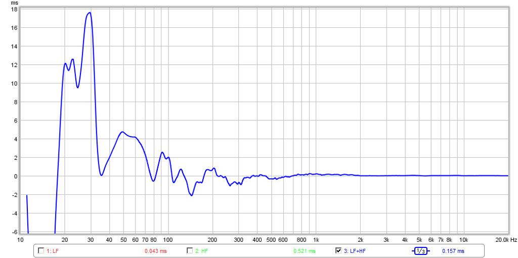
i´m amazed for the step plot, i haven´t got any similar
i´m amazed for the step plot, i haven´t got any similar
Do you have distortion graphs for this one?
i´m amazed for the step plot, i haven´t got any similar
Maninnen,
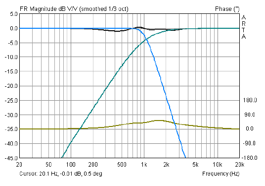
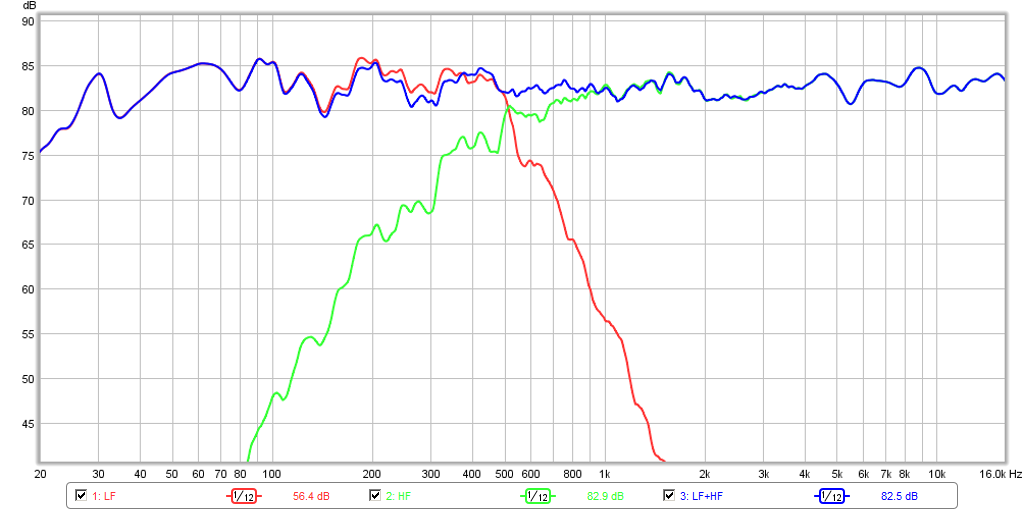
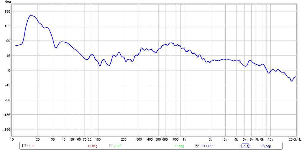
Thanks. You can get the step response if you use a very wide band mid and band pass it with 1st order Butterworth on both ends. Then low pass the woofer with Linkwitz Riley 2nd order and high pass the tweeter with Linkwitz Riley 2nd order as well. Now very important: all drivers are in phase with positive pushing drivers out. Next adjust delays between each separately. I start with woofer and mid first by setting sine generator at xo frequency and flip polarity of mid then adjust for minimum signal at xo frequency using and RTA. Then flip back and check to see if it looks good and smooth response through the xo range. Repeat for mid and tweeter. This should get you close - within 0.04ms then fine tune delay one increment at a time. Plot step response and tune as needed for best shape. I think I can improve it more. When you get it right the difference in percussive dynamics is like night and day. Good luck!
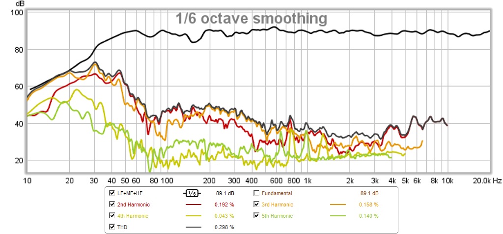
Here is HD, not the best I have seen as I think thin 3/8in thick ply baffle is vibrating and there are too many empty foam speaker boxes nearby resonating during the test.
Attachments
The latest baffle has two mids at like 300mm CTC separation. It means the beaming is rather drastic when xo is around 6kHz.
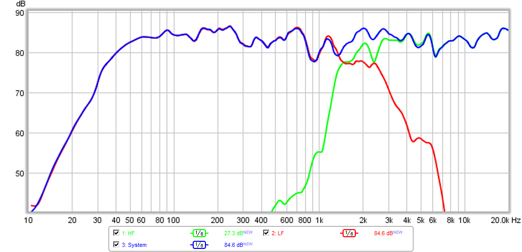
Here is Edge simulation at 2m distance, mic at other driver's on-axis 15cm/2m (only 3-5¤ off I guess) Crossing at 4kHz would be better, or the tweeter having less steep xo.
We always get compromised, don't we...
Here is Edge simulation at 2m distance, mic at other driver's on-axis 15cm/2m (only 3-5¤ off I guess) Crossing at 4kHz would be better, or the tweeter having less steep xo.
We always get compromised, don't we...
Attachments

Last edited:
The latest baffle has two mids at like 300mm CTC separation. It means the beaming is rather drastic when xo is around 6kHz.
Here is Edge simulation at 2m distance, mic at other driver's on-axis 15cm/2m (only 3-5¤ off I guess) Crossing at 4kHz would be better, or the tweeter having less steep xo.
We always get compromised, don't we...
Thanks for reminding me. I figured there was a magic number there. Maybe 3kHz even.
The latest baffle has two mids at like 300mm CTC separation. It means the beaming is rather drastic when xo is around 6kHz.
Here is Edge simulation at 2m distance, mic at other driver's on-axis 15cm/2m (only 3-5¤ off I guess) Crossing at 4kHz would be better, or the tweeter having less steep xo.
We always get compromised, don't we...
I just switched the XO to 400Hz and 3800Hz, and it sounds a lot better. Still tweaking the timing but noticing that shaping the tweeter's response in the stop band to remove a peak is helping to remove the pre-ring a lot.
I just switched the XO to 400Hz and 3800Hz, and it sounds a lot better. Still tweaking the timing but noticing that shaping the tweeter's response in the stop band to remove a peak is helping to remove the pre-ring a lot.
X hope i'm not wrong and irritating, intension is just to help and clear the message you did attend to Manninnen where you talked about XO for LF and HF was LR2 and MF was BW1 bandpass. These named acoustic textbook slopes is only present when you set gamma 1,0 in John Kreskovsky spreadsheet and at gamma 1,0 LF XO point is one octave less than MF center and HF XO point is one octave above MF center. Because your acoustic plots shown doesn't follow this scheme and new 400/3800Hz either, i point out that you no more at gamma 1,0 but use a lower gamma value and then slopes are no more textbook named corner frq knees LR2 for LF/HF and BW1 for MF but other un named ones.
At same ask if you have exported frd files from the spreadsheet and overlayed them in REW so you can hit the unique slopes needed for your lower gamma value with the purpose to widen mids bandwidth. Seems the math leading to transient perfect system you need have the exact slope as in the spreadsheet i think and not just some that looks alike 🙂. Say all this based your first attempt with TG9FD where a lot of time was wasted because polarization was accidently misunderstood and if you try hit LR2 textbook slopes for LF/HF XO points when your MF is widened (lower gamma value) you won't get the right filter math but instead need to import the un named slopes into REW and hit them.
I understand that for it to be perfect the slopes need to match textbook curves of 12dB/oct LR on woofer and tweeter and 6dB/oct BW on mid. However, what I found is that if you at minimum do it electrically, despite the final acoustic profile, you will sort of get a right triangle SR shape. It may not be as pretty as a "perfect" one - but it sounds a lot better than one that looks random up down like most multi-way speakers that are purely LR2 or LR4, etc. - even those with time alignment, they won't have the right triangle SR shape. So as a first cut, the electrical LR2-BW1-LR2 scheme seems to work.
I have found that with most drivers I have, even the very wide bandwidth TG9FD, it is nearly impossible to achieve 6dB/oct BW1 on the high pass side as that is the natural sealed box fall off. If you wanted to achieve that, it means not applying any high pass filtering on the mid which limits max power, and subjects it to IMD from large uncorntrolled bass motion. The tweeter is easy to get a true 12dB/oct LR2 curve and the woofer takes some work to get a LR2 low pass. The mid is problematic.
There is one interesting solution for users of DSP crossovers that is not actually transient perfect but quite close. For those wo understand French it can be found here (page 22):
http://petoindominique.fr/pdf/phase.pdf
For those who don't this is a quick and dirty description:
- take a fourth order Butterworth Lowpass with cutoff frequency fc
- take a 2nd order LR Highpass dimsioned for fc
- introduce a delay in the high-pass path equal to t=0.5/fc
The actual crossover frequency is a little higher than fc and the levels will be about 4 dB down at this frequency.
I know several people who have actually tried it (including the writer of that paper who also demoed it) and all were quite content. Because of the steeper slopes the inclusion of the natural driver respons(es) is a little simpler than for the filler-driver one.
Regards
Charles
Last edited:
xrk971,
I surrender you the one that have the real experience the two builds and good points you make that when SR looks as you have got it sounds a lot better than a random one.
My concern is if we forget John Kreskovsky spreadsheet a while and take example the B&O example i saw on PE forum. It says at center of MF lets say 1kHz you make LR2 for LF/HF then MF have BW1 500Hz and 2kHz bandpass and all drivers wired with normal polarity. Therefor real acoustic slope for LF and HF is not a LR2 because they cansel at 1kHz being 180º apart at XO point which leads to a acoustic slope that blend perfect with BW1 bandpass slopes down at 500Hz and up at 2000Hz. Yours is not following this scheme seen from plots regarding XO points and your new at 400/3800Hz. Afraid when you just simply space out LR2 XO points without using the spreadsheet slopes for other gamma value you end up a real acoustic LR2 that shall blend with BW1 slope which not sum perfect because you not have the correct cancel such out now that reformed LF and HF slopes to suit blend with BW1 for perfect sum.
@ XRK
Regarding your measurement set up (not a criticism as such):
Why not use the sofa cushions directly behind the mic. (yes I gather its cardioid /hyper cardioid but in the few (2/3 attempts) of measurement I have done, doing this cleaned things up quite a bit.
As someone else said in one of these recent threads, the x-y setup of the Zoom (assuming that's what you used here) will pick up much reflected sound from the room. Personally, I prefer the direct single mic on axis approach with a similar absorption panel begin the mic - the main difference in my case being a rear vented hyper cardioid mic (which has a narrow lobe in sensitivity at 180*)
Unsure if it is the same with cardioid mics in general however.
(sorry but I still loathe mini DSP 😉)
There is one interesting solution for users of DSP crossovers that is not actually transient perfect but quite close. For those wo understand French it can be found here (page 22):
http://petoindominique.fr/pdf/phase.pdf
For those who don't this is a quick and dirty description:
- take a fourth order Butterworth Lowpass with cutoff frequency fc
- take a 2nd order LR Highpass dimsioned for fc
- introduce a delay in the high-pass path equal to t=0.5/fc
The actual crossover frequency is a little higher than fc and the levels will be about 4 dB down at this frequency.
I know several people who have actually tried it (including the writer of that paper who also demoed it) and all were quite content. Because of the steeper slopes the inclusion of the natural driver respons(es) is a little simpler than for the filler-driver one.
Regards
Charles
This is very interesting, and may be able to explain why I was able to achieve near transient perfect response in the most unlikely place: a dipole z baffle speaker with a coaxial and K-aperture. Here, I used an LR2 electrical on both woofer and tweeter, yet somehow, the step response resembles a right triangle once the time delays were adjusted. A real head scratcher that I am thinking may have something to do with a phase reversal of the bass only with the K aperture? Although I am using 2nd order LR electrical, maybe when combined with natural response it resembles 4th order BW on tweeter. Then on woofer, it resembles 2nd order LR. I know this is flipped from the woofer and tweeter standpoint for 2nd and 4th order.
More here:
http://www.diyaudio.com/forums/full-range/271011-rockin-kazba-dipole-k-aperture-z-baffle-dipole-19.html#post4377787
Here is the xo plot from the above cited Harsch paper (note the resemblance to the KaZba xo but flipped for tweeter and woofer):
Here is the SR from the Harsch paper:

Given that the Harsch XO calls for a steep 4th order Bessel as the low pass on the woofer, this is great news as I want to really stomp out the cone breakup resonances on an aluminum woofer. I will try this out on my 10F/RS225 Ref Monitor next.
http://www.diyaudio.com/forums/full-range/273524-10f-8424-rs225-8-fast-ref-monitor.html
Attachments

Last edited:
This approach is step in transient perfect response, but the SR shown will have considerable overshoot and undershoot with square waves. Bessel functions have constant GD, and tweeter delay is partial compensation for woofer GD.
That approach appears to be related to the Jean-Michel Le Cléac'h quasi-optimal crossovers discussed in this thread:
http://www.diyaudio.com/forums/multi-way/231594-quasi-optimal-crossover-high-efficiency-loudspeaker-system.html
The emphasis there if I recall correctly was on low group delay rather than step response, and the systems were strictly 2-way rather than using the filler driver.
X, have you explored the JMLC crossovers?
Bill
There is one interesting solution for users of DSP crossovers that is not actually transient perfect but quite close. For those wo understand French it can be found here (page 22):
http://petoindominique.fr/pdf/phase.pdf
For those who don't this is a quick and dirty description:
- take a fourth order Butterworth Lowpass with cutoff frequency fc
- take a 2nd order LR Highpass dimsioned for fc
- introduce a delay in the high-pass path equal to t=0.5/fc
The actual crossover frequency is a little higher than fc and the levels will be about 4 dB down at this frequency.
I know several people who have actually tried it (including the writer of that paper who also demoed it) and all were quite content. Because of the steeper slopes the inclusion of the natural driver respons(es) is a little simpler than for the filler-driver one.
Regards
Charles
That approach appears to be related to the Jean-Michel Le Cléac'h quasi-optimal crossovers discussed in this thread:
http://www.diyaudio.com/forums/multi-way/231594-quasi-optimal-crossover-high-efficiency-loudspeaker-system.html
The emphasis there if I recall correctly was on low group delay rather than step response, and the systems were strictly 2-way rather than using the filler driver.
X, have you explored the JMLC crossovers?
Bill
No, I have not heard of the JMLC XO. I will look at the thread you cite.
The emphasis there if I recall correctly was on low group delay rather than step response, and the systems were strictly 2-way rather than using the filler driver.
A speaker with a perfect step response does not have any group delay distortion. The Le Cleach crossover and the one shown by Samuel Harsch reduce group delay distortion. I.e. they are somewehere inbetween a classic all pass crossover and a transient-perfect crossover in terms of time domain distortion.
The advantage of these intermediate aproaches is that they can easily be implemented using fairly ordinary drivers and DSP crossovers that are not freely programmable. As soon as you are not restricted by the capabilities of these DSP GUIs anymore you have of course another set of powerful tools in your hand like subtractive-delay crossovers and FIR filters.
Regards
Charles
I modeled the 2-way Harsch XO with PCD and FRD files for the RS225-8 and ScanSpeak 10F/8424 in my 10F/RS225 FAST Ref Monitor using 400Hz electrical xo frequency. Looks promising.
More here:
http://www.diyaudio.com/forums/full...-rs225-8-fast-ref-monitor-64.html#post4398272
More here:
http://www.diyaudio.com/forums/full...-rs225-8-fast-ref-monitor-64.html#post4398272
Harsch XO implemented with 10F/8424 & RS225-8 2-way
I implemented the Harsch XO using my 10F/RS225 FAST Ref Monitors:
http://www.diyaudio.com/forums/full-range/273524-10f-8424-rs225-8-fast-ref-monitor-65.html
Phase:
Group Delay:
Step Response:
Sounds very nice, not perfect step but great compared to LR2-LR2.
I implemented the Harsch XO using my 10F/RS225 FAST Ref Monitors:
http://www.diyaudio.com/forums/full-range/273524-10f-8424-rs225-8-fast-ref-monitor-65.html
Phase:
Group Delay:
Step Response:
Sounds very nice, not perfect step but great compared to LR2-LR2.
I've been simulating this in MATLAB since i've been curious as to how severe the effects of driver limitations are i.e. how closely the drivers need to follow the target slopes to achieve linear phase.
For a 3-way, I found the crossover points need to be overlapped and the level of the mid/filler driver increased slightly to achieve proper summing.
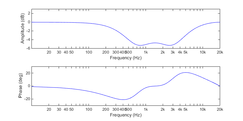
Simply designing a conventional 3-way with LR2 slopes on the woofer/tweeter and BW1 slopes on the mid will cause a recession in the midrange and some swings in the phase response:
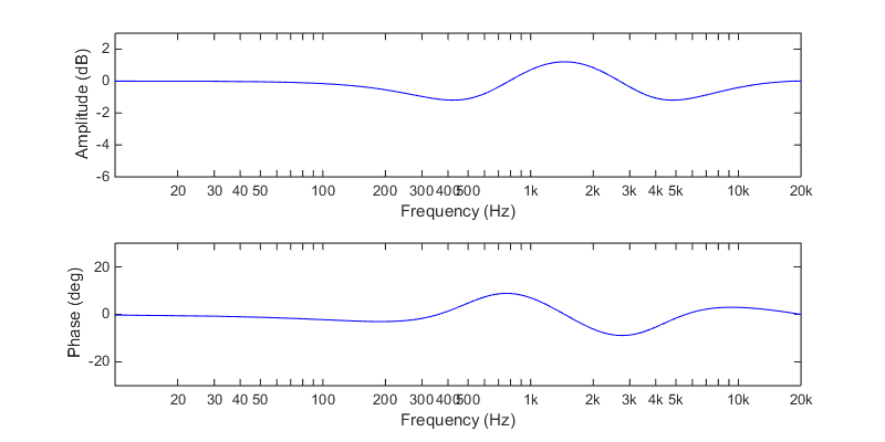
Adjusting the mid level up about 4-5dB helps, but it's still not perfect:
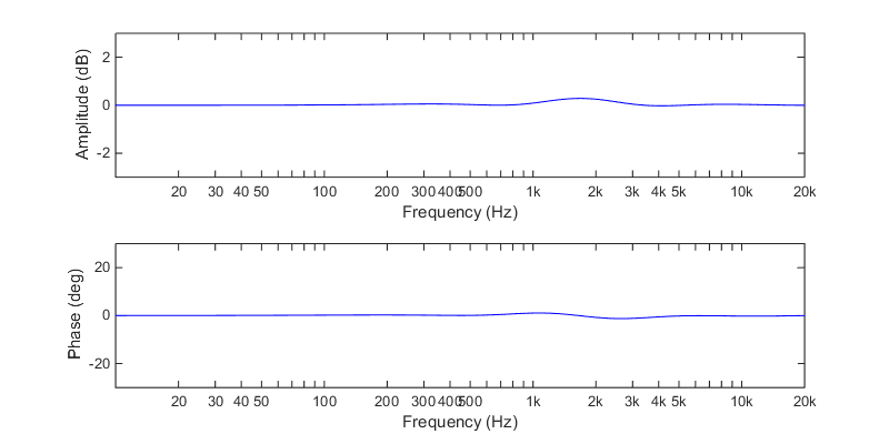
Here we have LR2 950Hz on the woofer, BW1 700Hz/4KHz on the mid and LR2 3KHz on the tweeter. The level of the mid is adjusted +3.5dB relative to the levels of the woofer and tweeter:
Looks pretty good so far, what happens if I add BW2 highpasses to the mid and tweeter at 200Hz and 1KHz respectively to simulate the natural roll off of the drivers? (Note: Change in amplitude scaling)
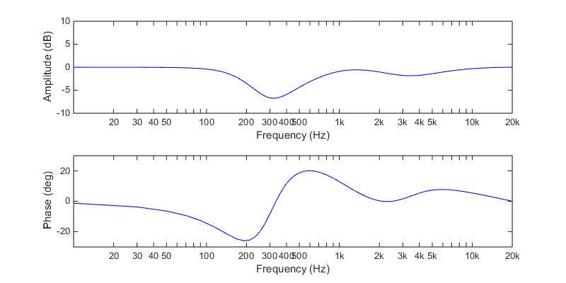
Not ideal, but still quite linear compared to a conventional 3-way XO
edit: actually may have been a slight screw up in the simulation. Redoing a few things now. Edit2: updated.
For a 3-way, I found the crossover points need to be overlapped and the level of the mid/filler driver increased slightly to achieve proper summing.
Simply designing a conventional 3-way with LR2 slopes on the woofer/tweeter and BW1 slopes on the mid will cause a recession in the midrange and some swings in the phase response:
Adjusting the mid level up about 4-5dB helps, but it's still not perfect:
Here we have LR2 950Hz on the woofer, BW1 700Hz/4KHz on the mid and LR2 3KHz on the tweeter. The level of the mid is adjusted +3.5dB relative to the levels of the woofer and tweeter:
Looks pretty good so far, what happens if I add BW2 highpasses to the mid and tweeter at 200Hz and 1KHz respectively to simulate the natural roll off of the drivers? (Note: Change in amplitude scaling)
Not ideal, but still quite linear compared to a conventional 3-way XO
edit: actually may have been a slight screw up in the simulation. Redoing a few things now. Edit2: updated.
Last edited:
- Status
- Not open for further replies.
- Home
- Loudspeakers
- Multi-Way
- "Filler" driver ala B&O