Hi guys it's been awhile, I know you can find the amplification factor by doing a little math I just don't remember how you do it can anyone remind me?
Thanks a mill,
Nick
Thanks a mill,
Nick
Easy. Look it up on the datasheet.
Otherwise, the mu is the slope of plate voltage change plotted against grid voltage change at constant plate current. If you have the curves in hand (but for some odd reason can't turn back a page to get the mu), lay a horizontal line across the curves at the planned current. Find the curve that's closest to the desired no-signal plate voltage and note the reguired grid voltage. Step over one curve and read off the plate voltage and note the grid voltage. Take the difference between the two plate voltages and divide it by the difference between the two grid voltages. Voila! You have mu.
Otherwise, the mu is the slope of plate voltage change plotted against grid voltage change at constant plate current. If you have the curves in hand (but for some odd reason can't turn back a page to get the mu), lay a horizontal line across the curves at the planned current. Find the curve that's closest to the desired no-signal plate voltage and note the reguired grid voltage. Step over one curve and read off the plate voltage and note the grid voltage. Take the difference between the two plate voltages and divide it by the difference between the two grid voltages. Voila! You have mu.
Well the funny problem is the spec sheet for the tube besides the voltage a current limits only lists the mutual conductance and here's another shocker no graphs.
Thats why I asked and just in case you want to look it up the tube is a gu10a.
Nick
Thats why I asked and just in case you want to look it up the tube is a gu10a.
Nick
Oh I forgot to ask is the mutual conductance the same as the mu?
I have a strange feeling that it is and im going to feel a little stupid.
Nick
I have a strange feeling that it is and im going to feel a little stupid.
Nick
They call it "gain coefficient" on the data sheet. 40-45.
Mutual conductance is the same as transconductance, i.e., it's the change in plate current with change in grid voltage, at constant plate voltage. Mu is the product of transconductance and plate resistance.
Mutual conductance is the same as transconductance, i.e., it's the change in plate current with change in grid voltage, at constant plate voltage. Mu is the product of transconductance and plate resistance.
Ah I didn't know it was that thanks SY
But as you can see there isn't a lot of data of the spec sheet.
Thanks,
Nick
But as you can see there isn't a lot of data of the spec sheet.
Thanks,
Nick
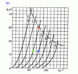
Hi Nick,
When you have plate curves, you have all !
In attached one (It's a Russian 6N6pi)
Pick a first point on a grid line, f.e. the red one where Vg is -4V, Vp is +155V and Ip is 30mA
Move down vertically (constant plate voltage) till you cross another grid line (the blue dot).
Here Vg is -6V and Ip is 12 mA.
That means that plate current change is (30 -12) 18mA for Vg change of 2 Volts.
Thus the slope is (18 / 2) 9mA per Volt, the same that a transcondustance of 9000 if expressed in mmoh.
Then, move left horizontally (constant plate current) till you meet the original grid line (green dot).
The plate voltage is now 120V for a 2V grid voltage difference, thus the Mu, µ or amplification coefficient is (155-120) / 2 = 17.5
The Rp is figured by the slope of a straight line joining the red and the grid dot.
This is the same as dividing the Mu by the slope (in Ampere per Volt), here 17.5/.009 = 1K94.
<edit>
Oopps, misread the plate voltage !
</edit>
Yves.
Attachments
I know I wish the tube spec sheet had them. I have faced the facts and relised I will had to use the data I have from the data sheet and try to make my self a plate current per plate volt by grid voltage chart my self.
SY don't worry I am not thinking of using this tube for a audio amp.
Nick
SY don't worry I am not thinking of using this tube for a audio amp.
Nick


Sy you would like the tube I got yesterday then,it's a 5762 which is a triode made by rca for vhf tv transmission it ha a 4kw anode diss. But the nice this about it is it's super low anode resistance which at 4 kv b+ is just over 1k.
It's not speced for class a but at 4kw anode dissipation and with low b+ I bet it could handle it just fine.
It's a pricy tube new though just shy of 2 grand.
Nick
It's not speced for class a but at 4kw anode dissipation and with low b+ I bet it could handle it just fine.
It's a pricy tube new though just shy of 2 grand.
Nick
Yeah, we're looking for a tube like that which we would find in a garage sale and give the grateful seller $20. 
HaHa Thats about how much I payed for it. The guy didn't even know what tube it was.
I just fired itup tonight and I got emission so I'm happy.
Nick
I just fired itup tonight and I got emission so I'm happy.
Nick
Oh Sy I dout you could find one but check out this tube 8d21.
It would make one heck of an amp or 2.
Nick
It would make one heck of an amp or 2.
Nick
Well I was wrong, I tested the tube with b+ and even just 600 vdc it would flash over so I guess it's a paper weight.


Nick
Nick

- Status
- Not open for further replies.
- Home
- Amplifiers
- Tubes / Valves
- figuring amplification factor of a tube