In the building doc you can read use 2 spacers between tranny and board acting as standoff.I'm using a aluminium oxide isolator of 3mm between the sink and tranny this way my board is 1 cm distance from the sink.I'm planning to srew the tranny flat against the board or would that be a bad idea?
Yes. There are terminations on the underside of the board which may interfere with the top of the output device; notably the leads of D1 and D2.
You really should use some form of spacer, even 1.5mm of spacer is sufficient.
Cheers,
Hugh
You really should use some form of spacer, even 1.5mm of spacer is sufficient.
Cheers,
Hugh
Hugh,I've checked this and D1-2 ain't interfering the trannies at all cause I use the TO-247 Fets.Minimum 3 mm distance from the leads.
My concern is will the fets heat up the board in a dangerous way.Pointing out my question also to AndrewT
Edit : did use the spacers anyway,now there will be an airflow between the board and the top of the trannies
My concern is will the fets heat up the board in a dangerous way.Pointing out my question also to AndrewT
Edit : did use the spacers anyway,now there will be an airflow between the board and the top of the trannies
Last edited:
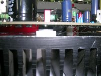
That looks fine, MM.
Heat won't hurt the pcb, however, I prefer to have some air above the fets to improve cooling on both sides. If the fet is hard up against the pcb, ventilation is much reduced.
Cheers,
Hugh
Heat won't hurt the pcb, however, I prefer to have some air above the fets to improve cooling on both sides. If the fet is hard up against the pcb, ventilation is much reduced.
Cheers,
Hugh
You can use 6.3A or 5A fuses, MM, no problem. Is it the size, or the capacity which is making it difficult?
These are 3AG, not M205, which I understand Europe is using these days. The physical size of the fuse is not important, only the rating.
Cheers,
Hugh
These are 3AG, not M205, which I understand Europe is using these days. The physical size of the fuse is not important, only the rating.
Cheers,
Hugh
5 or 6 isn't a problem I'll take one of those.One question remains,with a 25Vac transformer the voltage across the bootstrap resistor (R12) needs to be between 24-26 volts.But I'm planning to use a 24 Vac transformer,is it still the same or do I set it at 23-25 volts?
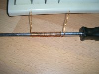
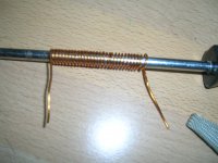
It seems the coil is wounded the wrong way
It seems the coil is wounded the wrong way
Attachments
Last edited:
Yes, MM, your voltages are about right.
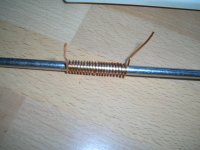
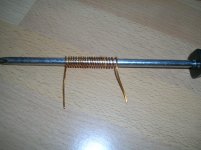
When you wind the inductor, hold screwdriver in RIGHT hand, with wire in LEFT hand.
Now, position start of wire at right, on top of the driver, and wind towards, down, under and back to the top, towards you for the next turn, and so on. That will ensure the correct technique......
Cheers,
Hugh
When you wind the inductor, hold screwdriver in RIGHT hand, with wire in LEFT hand.
Now, position start of wire at right, on top of the driver, and wind towards, down, under and back to the top, towards you for the next turn, and so on. That will ensure the correct technique......
Cheers,
Hugh
Why are 5A, 6.3A & 7.5A fuses necessary?
Surely this amplifier will operate properly into the correct speaker loading with much lower rated fuses.
Surely this amplifier will operate properly into the correct speaker loading with much lower rated fuses.
Maybe silly question,where do I connect my multimeter probes for bias setting Tp1 and Tp2 ? Or across R18 and or R17 ?
- Home
- More Vendors...
- AKSA
- Fetzilla Build Documentation